| GISdevelopment.net ---> AARS ---> ACRS 2004 ---> New Generation Sensors and Applications: New Generation Sensors |
Calibration Methodology for
Laser Scanner External Parameters
Masahiko Nagai, Ryosuke
Shibasaki, Dinesh Manandhar
Center for Spatial Information Science, The University of Tokyo
Cw-503, IIS, 4-6-1, Komaba, Meguro-ku, Tokyo 153-8505, Japan
Tel: +81-3-5452-6417 Fax: +81-3-5452-6414
E-mail: nagaim@iis.u-tokyo.ac.jp
Center for Spatial Information Science, The University of Tokyo
Cw-503, IIS, 4-6-1, Komaba, Meguro-ku, Tokyo 153-8505, Japan
Tel: +81-3-5452-6417 Fax: +81-3-5452-6414
E-mail: nagaim@iis.u-tokyo.ac.jp
ABSTRACT
In order to present a space in details, it is indispensable to acquire 3D information. Laser scanner is one of the most effective tool for acquiring 3D information. For 3D measurement by a laser scanner, it is necessary to conduct sensor calibration to know the relative position and attitude against other positioning sensor. However, quick and handy method of a laser scanner calibration did not exist, because laser beam is invisible for human eyes and it is very difficult to see whether the center of a laser beam exactly hit upon control points. In this study, we propose a new method of calibration to determine the external orientation parameters of a laser scanner using a solar cell connected to an earphone for laser beam detection. If the laser beam hit the solar cell, beep sound let us know it does. By finding out the location of maximum sound level, the center of laser beam can be located for calibration even though laser beam is invisible. Through the experiment with this method, it is concluded that the external orientation parameters of laser scanner can be determined, and it helps to combine a laser scanner with a digital camera or IMU easily for simple 3D measurement.
1. INTRODUCTION
A lot of researches are conducted for acquiring 3D spatial information by using photogrammetric methods. With this method, 3D information is extracted by stereo matching, but this method is very difficult to automate in certain measurement conditions because of shadows or occlusion of features. On the other hand, a laser scanner can directly measure 3D shape of a target feature automatically. Laser scanner has been successfully applied in many applications. Furthermore, with the development of technology, a laser scanner become cheaper. Nowadays, some laser scanners can be purchased in few thousands of US dollars. That is, a laser scanner can be used for 3D measurements easily.
In case of 3D measurement by a laser scanner, it is indispensable to conduct external calibration against other positioning sensor (Manandhar and Shibasaki, 2002). However, a laser beam of a laser scanner is invisible, that makes it impossible to directly apply such control points as used for the calibration of CCD camera. Thus, it is difficult to check whether a laser beam hits on targets or not. In this research, a new methodology for the external orientation of laser scanner using a solar cell is proposed.
2. CHARACTERISTICS OF LASER SCANNER
2.1 Laser Scanner
Laser scanner is operated by measuring the time flight of laser light pulse. A pulsed laser beam is emitted and reflected. After laser beam meets an object, the reflection is received. The time between transmission and reception is proportional to the distance between laser scanner and an object. The laser beam is deflected by an internal rotation mirror. A fan-shaped scan is made of the surrounding area. The contour of the target object is determined from the sequence of impulses received. In this research, LMS-291, SICK, is used. Table 1 shows basic specifications of LMS-291.
2.2 Spot Diameters and Intervals
In a radial field of vision, a light impulse is emitted every 0.25º in this research. As a result of the beam geometry, the spots overlap on the target object. Figure 1 shows spot diameters and intervals in relation to the range.
Figure 1 Diameter and Interval of Spot
3. SETTING OF CONTROL POINTS
3.1 Location of Control Points
In this research, target points are put on glass, because laser beam can penetrate the glass plane.
Figure 2 shows the image of target points on the glass plane. If a laser beam hits the target point, it reflects on the glass plane. If a laser beam doesn’t hit the target point, it penetrates the glass plane. That is, it can be recognized whether a laser beam hits the target point or not. Therefore, target points on the glass plane can be used as control points for accurate laser scanner calibration, if we can be sure that the center of a laser beam hit exactly upon the center of the control points.
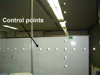
Figure 2 Setting of Control Points
3.2 CoBIT
As shown in Figure 1, the size of laser spots is large enough and we need to exactly located the center of the laser beam on the target object. It is necessary to find the way to make sure that the center of each laser spots hit the center of laser target. In previous researches, IR scope was used to visualize the laser spot. However, eye safe laser used for ordinary ground-based laser scanners is very week in energy intensity that makes it very difficult to see laser beam by IR scope.
In this research, CoBIT (Compact Battery – less Information Terminal) is used (Nishimura, T., Itoh, H. et al., 2004). It has a solar cell and can receive a modulated light including encoded information. That is, a CoBIT can communicate with the otherl system and with the users by the energy supply from the environment.
CoBIT consists of a solar cell connects directly to an earphone which generates sounds, as shown in Figure 3. If the solar cell received laser beam from a laser scanner, the earphone beeps. The center of laser beam can be rather accurately located by finding put a location where the beep sound become the loudest even though the laser beam is invisible.
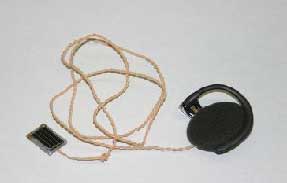
Figure 3 CoBIT
4. MEASUREMENTS
4.1 Measurement by Laser Scanner
Target points are measured by the laser scanner. These target points are already set on the center of each laser spots by using CoBIT. Figure 4 shows the result of laser scanning. X axis is the distance from laser scanner to target points. Y axis is the observation width. As shown in Figure 4, it can be clear that 8 control points are set on the glass plane. Table 2 shows the laser scanner coordinate (Xl, Yl, Zl) of each control points which are measured by the laser scanner. Scan line of laser scanner must be straight, so height (Zl) must be zero in the laser scanner coordinate.
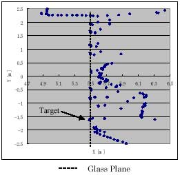
Figure 4 Laser Scanning
4.2 Measurement by Total Station
In order to decide exact coordinate value of control points, control points are measured by total station. The result of measurement is shown in Table 3 as the total station coordinate (Xt, Yt, Zt).
This is the true value of the control points as the fiducial coordinate. Figure 5 and Figure 6 show the graphs of the result of Total Station.
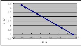
Figure 5 Result of Total Station (Xt, Yt)
Figure 5 shows the graph for (Xt, Yt). The locus of laser points must be straight because control points are put on the glass plane as shown the relationship between Xt and Yt in Figure 5. On the other hand, the locus of laser points of Xt and Zt in Figure 6 is not straight. This is due to the error of control points setting, that is, the error in locating the center of laser beam with CoBIT. As above, because laser scan line is straight, the regression line of control points is estimated and Xt and Zt values of control points are fitted on this regression line. Regression equation of Xt and Zt is shown in Figure 6.
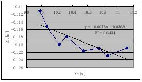
Figure 6 Result of Total Station (Xt, Zt)
According to this experiment, this setting error is approximately 4 mm in maximum which is very accurate. Therefore, by using CoBIT, the most ideal regression line can be estimated.
4.3 Coordinate Conversion
In this research, 3D Helmert’s transformation equation, Equation (1), is used to estimate laser scanner external parameter. The laser scanner coordinate (Xl, Yl, Zl) are converted to the total station coordinate (Xt, Yt, Zt). Scale factor (s), rotation matrix (R), and shift vector (Tx, Ty, Tz) are estimated by least square method. Table 4 shows the result of this calibration methodology to find the laser scanner external parameters.
5. Conclusion
Laser scanner calibration is not easy, because laser beam is invisible, where wave length is approximately 905 nm±10 nm. In this research, the solar cell earphone, called CoBIT is used for laser scanner calibration. If the solar cell detect laser beam from laser scanner, the earphone makes beep sound. Therefore, the exact location of laser beam center can be measured for calibration even though laser beam is invisible. External parameters of laser scanner are estimated by computing the scale factor, rotation matrix and shift vector by converting the laser scanner coordinate to the total station coordinate which is the fiducial coordinate. In this research, the setting error can be reduce down to 4 mm by CoBIT. According to this calibration methodology, external parameters of a laser scanner can be decided accurately, and it helps to combine a laser scanner with a digital camera or IMU easily for simple 3D measurement.
References
- Manandhar, D., Shibasaki, R., 2002. Auto-Extraction of Urban Features from Vehicle-Borne Laser Data, ISPRS, ”GeoSpatial Theory, Processing and Application”, Ottawa.
- Nishimura, T., Itoh, H., Nakamura, Y., Yamamoto, Y., Nakashima, H., 2004. A Compact Battery-Less Information Terminal for Real World Interaction, PERVASIVE, Springer L NCS3001, pp.124-139.