| GISdevelopment.net ---> AARS ---> ACRS 2004 ---> Data Processing: High Resolution Data Processing |
Automated Procedure of a
Prototype Mapping System
Yubin Xin and Doug
Parent
PCI Geomatics Inc.
50 West Wilmot St., Richmond Hill, Ontario L4B 1M5, Canada
Fax: 1-905-7640153,
Email: xin@pcigeomatics.com and parent@pcigeomatics.com
PCI Geomatics Inc.
50 West Wilmot St., Richmond Hill, Ontario L4B 1M5, Canada
Fax: 1-905-7640153,
Email: xin@pcigeomatics.com and parent@pcigeomatics.com
Abstract
Maps generated from satellite imagery and airborne data of various resolutions are an extremely useful reference that provides detailed topographic, land-use and land-cover information. With the growing supply of quality image data and demand for up to date maps, an automatic technique to correct imagery and generate maps is necessary. This paper presents a system that can generate/update maps automatically using satellite images or aerial photographs. This technique makes full use of georeferencing and sensor model information such as ephemeris data, geometric model, and/or GPS/INS positioning information, to automatically correct and geocode the raw image data. Furthermore, an automatic mosaicking process that can generate optimized cutlines, perform color balancing, and remove hot spots, is used to generate a seamless mosaic image or image tiles. This paper briefly introduces global mapping system concepts that form a part of a map production workflow. It describes the image correction methodology including:
- Automatic Ground Control Point (GCP) collection from:
- Existing geocoded images,
- Reusable GCP chip databases, or
- Raw images with precise sensor model
- Automatic GCP error detection
- Sensor model refinement
- Orthorectification, and
- Automatic cutline selection, and color balancing for seamless mosaicking
1. Data Preparation
The image import component can automatically identify the file structure of a stored set of raw image data and convert information to a known format. A DEM can be obtained in various ways, for example it can be acquired directly from third party providers, or it can be generated by software with stereo image data sources.
The approximate georeferencing models are obtained from the ephemeris/orbital data for satellite images or from the GPS/INS data for aerial photographs. GCPs, which inherently contain both image and ground coordinates, are required to detect blunders, to control the model quality, and to refine the approximate model to achieve a high-precision georeferenced result. For the purpose of improving efficiency and for automating the procedure, we select and store a set of GCPs in a database structure. All the relevant information about a GCP and the neighboring pixels that surround the GCP are included as the structure data. This structured data is called a GCP chip, while the database is called the GCP chip database. The purpose of using a GCP chip database is to permanently store GCP chip information that can be easily accessed and reused with new images in an automated procedure. We have various options to create a chip database: manually extract in an interactive environment, automatically extract from orthorectified images, or from raw images with precise math models and corresponding elevation information.
2. Image Registration
The georeferencing model relies on two sets of data: camera/sensor information to set up the mapping equation, and GCPs to refine the parameters in the model. During the modeling stage, both forward and backward transformations between the raw pixel and line coordinates and the georeference coordinates can be established. The GCPs are used to refine the approximate model to achieve a precise georeferencing result and to detect blunders
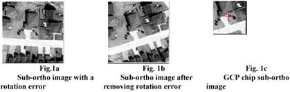
In automating the procedure, the main problems we met with were geometric deformation and/or clouds on the raw image. Clouds on the image cause mismatching in the correlation step and also affect the radiometric balancing algorithms. The geometric deformation in some extreme cases is so serious that the pixel ground resolution at the edge of a raw image is almost two times that of the center, and the orientation for each pixel is dependent on its position in the image. To solve these issues, a special procedure was developed. When the GCP chip database is obtained for the area, we orthorectify a sub-area from the raw image by using the initial georeferencing data, the elevation, and the pixel sampling distance (PSD) from the GCP chip structure to make both the sub-orthos and the chip images in the same reference surface and resolution. This process can greatly reduce the affects of geometric deformation. After this preparation, we are ready to perform the critical matching procedure to register each individual GCP chip onto the sub-ortho image, and project into the raw image. Assuming all the GCPs are located on edge corners, We set up the following hypothesis between the sub-ortho image and the chip image:
- They have same edge features and similar corner points.
- The GCP should be located on or very close to one of the extracted corner positions.
- There is the same number of intersected edge lines crossing the corresponding GCP point. And, those conjugate linear edge features have similar geometric and radiometric characterizations.
- Violation to any one of the matching criteria leads to an incorrect match and the candidate position should be filtered out from the matching list.
- Successfully passing all the matching criteria results in a correct position.
Edge detection To locate each edge precisely, We firstly check and preprocess the raw image quality. If a raw image data contains noise and blurriness, a Gaussian smoothing is performed on the sub-area . Then the gradient in horizontal, vertical, and diagonal directions are calculated and stored for both edge detection and corner detection. In the edge detection step, weak edges (and also weak corners) always exist. To avoid skipping those features, we consider about all the four directional gradients and compare them with corresponding thresholds to decide each edge pixel. The output of the gradient edge detection is a binary edge image but it may contain wide ridges around the local maxima. The required final position of the edge lies approximately in the middle of this wider edge [3]. To extract the central position of the edge, a thinning (or skeleton) filter is applied. We have implemented the Kreifelts [4] algorithm to filter out non-skeleton pixels.
Corner detection Since a GCP is always located near a corner feature, we can capture corner structures in patterns of intensities [Trucco]. Using the gradient images, we immediately calculate the eigenvalues of a sum-gradient matrix C. Comparing the minimal of the two eigenvalues with a pre-defined threshold, we may decide the candidate corner position.
Azimuthal characterization matching is an algorithm that was first proposed by Motrena et al [6]. The approach is to solve the rotation-variant problem existing in area-based correlation method. It is based on the autocorrelation function of one azimuthal projection around a candidate GCP and has rotation and contrast invariances.
If an orientation variance (rotation) exists, the azimuthal projections of the sub-ortho image and the GCP chip image about the corresponding central pixels will differ by a phase factor: the sets are the same but the initial elements are different [6]. We may apply the autocorrelation function [6] to determine the rotation angle:
Linear feature extraction and comparison
To improve the robustness, we add line comparison in the neibourhoods of the candidate point and of the GCP position in the chip. The Hough Transform line detection is performed in the thinned edge image surrounding those two positions. Usually there is two to four line sections in each patch that can be found. We can directly compare their slopes and/or the lengths and the brightness between the conjugate features to filter out mismatching.
Pyramid cross-correlation
Based on the rotation angle and the initial camera/sensor model, we may need to re-calculate the resampling to generate the sub-ortho image for each GCP chip, then perform coarse correlation and fine correlation in a hierarchical match process. The matched position is back projected onto the raw image. Figure 1 shows orthorectified image patches and a GCP chip.
3. Model Construction and Refinement
The mathematical model relies on two sets of data: orbit/sensor information to set up the mapping equation, and ground control points to refine the parameters in the model.
The structure of the math model varies with the different sensors. The sensor models define the mapping between raw image coordinates and a reference coordinate frame of the sensor, together with the imaging time. The orbital model encapsulates all knowledge about the characteristics of the satellite position and attitude in its orbit, over the image of interest. The model corrected or constructed with the ground control points forms the basis of precision mapping.
4. Orthorectification and Mosaic Generation
With an accurate georeferencing model for each image and a Digital Elevation Model for the working area, we can generate orthorectified images. Because of the existence of inconsistent radiometry, we may perform hot spot removal and radiometric balancing on the orthorectified images, and then merge them into an image map.
Hot spots can be described or represented as a 3D ellipsoid located on an image. The third dimension represents the intensity variance. The parameters of this model can be calculated through a least squares algorithm. Using the obtained parameters we can reduce or eliminate the hot spot effect. When inconsistent radiometry exists between images, we have to apply radiometric balancing. A global bundle calculation is performed based on overlapped areas to figure out a set of correction parameters or lookup table for each image. Cutline selection is one of the most important steps. An optimization model for computing cutlines can be set up, which includes a cost function of a criteria and a set of constraints. We use optimal programming to solve the model and get polygon shaped cutlines for each ortho image. Pixels inside the cutline will contribute to the final mosaic image.
5. Example and Application
We have developed a prototype of an automatic image correction and mapping procedure in a Python PPF (PCI Pluggable Functions) environment. This is a fully automatic processing system with Python script batch processing environment supported by PCI Dynamically Linked Library (DLL). One study area is in Ontario, the other is in British Columbia. The satellite images are 15 m Pan-chromatic (PAN) and 30 m Multi-Spectral (MS) color imagery. Chip database contained various resolution image chips in both areas. DEMs are 30 m USGS DEM.
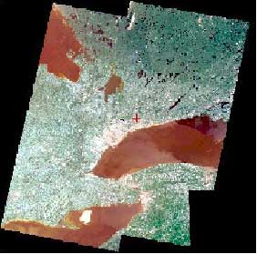
After automatically collecting GCPs, a rigorous sensor model was constructed for each image. The images were then orthorectified and a Pan Sharpening process was performed to fuse the multi-spectral and panchromatic imagery to obtain Pan-Sharpened orthorectified images. Finally, we mosaicked the orthorectified images into a large raster mosaic map, with hot spot removal and histogram color balancing processing. Figure 2 shows the mosaic, which consists of four Pan Sharpened images.
6. Conclusion
The automatic procedure described above has been developed and implemented in PCI's software product. The experiment shows very positive result in terms of efficiency, reliability and accuracy. Through the development, implementation, and analysis of the results, the following conclusions are made:
- The presented automatic procedure is implemented for fast, accurate, efficient and reliable image map generation, in a Python environment.
- The technique has been successfully applied on various types of imagery.
- The system is able to process a large data set fully automatically.
- The procedure produces high quality image maps.
- Although the whole procedure is highly automatic, some options and interaction are still required to guarantee the product quality.
- Eidenshink, Jeffery C., 1992. The 1990 Conterminous U.S. AVHRR Data Set, Photogrammetric Engineering & Remote Sensing, 58(6): 809-813.
- Greenfield, J.S., 1989. Experiments with Edge-Based Stereo Matching, Photogrammetric Engineering and Remote Sensing, 55(12): pp1771-1777.
- Heipke, C., 1995. State-of-the-Art of Digital Photogrammetric Workstation for Topographic Applications, Photogrammetric Engineering and Remote Sensing 61(1): pp49-56.
- Kreifelts, T., 1977. Skelettierung und Linienverfolgung in raster-digitalisierten Linienstrukturen, in Nagel, H.-H. (Ed.), Digitale Bildverarbeitung, pp223-231
- Lemmens, M., 1988. A Survey on Stereo Matching Techniques, International Achieves of Photogrammetry and Remote Sensing, Commission V, 27(B8): 11.
- Motrena, P. and Rebordao, J.M., 1998. Invariant models for ground control points in high resolution images, International Journal of Remote Sensing, 19(7): 1359-1375.
- Schenk, T. 1999. Digital Photogrammetry, V1, TerraScience. Trucco, E. and A. Verri, 1998. Introductory Techniques for 3-D Computer Vision, Prentice Hall.
- Xin, Y. and Lu, F., 1998. Automating the Procedure for Constructing Georeference Model on Raw Images, Proceedings of Spatial Information Science, Technology and ITS Applications ISPRS, pp260-265
- Xin, Y. and Cheng, P., 2001. Automating Image Map Generation Using Satellite Images and Aerial Photos, Proceeding of the 21 st International Cartographic Conference
- Zlotnick, A. and Carnine, P.D. 1993. Finding Roads in Aerial Images, Computer Vision, Graphics, Image Processing: Image Understanding, 57(2): pp243-260.