| GISdevelopment.net ---> AARS ---> ACRS 2004 ---> GPS & Photogrammetry: Digital Photogrammetry |
Sparse GCPs supported
high-resolution airborne SAR triangulation test in China
Pang Lei, Zhang Jixian, Yan
Qin
Institute of photogrammetry and remote sensing
Chinese Academy of Surveying and Mapping
Beitaiping road 16, Haidian district, Beijing, P. R. China 100039
Phone :+86 10 88229545 ,Fax :0086 10 68211420
E-mail: Panglei.mail@163.com, stecsm@public.bta.net.cn
Zhang Mingbo
Institute of Geographical Sciences and Natural Resources Research, CAS
Datun Road 3, Chaoyang district, Beijing, P. R. China 100101
Phone: +86 10 64861632 -184, Fax :0086 10 64851844
E-mail: zhangmb@lreis.ac.cn
ABSTRACT
Presently, high-resolution airborne SAR imagery has often been chosen as the irreplaceable remote sensing data resource in mapping some cloudy or soupy mountainous areas. At the same time, the mission that how to acquire enough accuracy and quantity of ground control points (GCPs), which are difficult to be measured practically, has become an urgent demand for mapping tasks. This paper discusses the aerial triangulation mathematical model from airborne SAR images, with which only sparse GCPs are available. And, with navigation data provided from GPS/INS system, it puts forward the corresponding technique flows. Lastly, the high-resolution airborne SAR triangulation test in Zhengzhou, China, was introduced to validate the model. In the test, we utilizing X-band, single antenna SAR sensor to acquire 1m resolution airborne SAR remote sensing imagery, and the corresponding DGPS and INS data synchronously. And under the condition of sparse GCPs available, combining with the SAR imaging equation, we computed directly the ground coordinates of target points by multi-paths block adjustment. And , the first test results have been presented.
1 INTRODUCTION
The technique problem that how to acquire enough accuracy and quantity of ground control points (GCPs), which are very difficult to be measured practically, has become an urgent demand for future mapping tasks. Although, the study to decrease the demand of GCPs in mosaic of RADARSAT or ERS SAR images or acquiring dense GCPs network has been done by Denise (1998), Belgued (1998) and Toutin (2003 )et al 1~6 , there has no corresponding study on the method or models of high-resolution airborne SAR images triangulation.
Comparing with satellite-borne SAR images triangulation, the essence of high-resolution airborne SAR triangulation is still the 3D space positioning from SAR images (Chang, 2002) 7 , which supported by only sparse GCPs or without GCPs. But, the method and mathematic models must be based on the characteristics of airborne SAR imaging conditions and flight tracks. So, we put forward the corresponding mathematic models supported by DGPS/INS, and introduce the high-resolution airborne SAR triangulation test in China in the following parts.
2 SAR TRIANGULATION VECTOR MODEL
Generally, an airborne mapping system is integrated with carrier phase differential GPS (DGPS) and precision inertial navigation system (INS), which can realize the geocoding of remote sensing imagery directly. And, for the SAR imaging system, they are often applied in motion compensating in SAR imaging processing. Here, considering only sparse GCPs available in the mapping of some areas difficult to be surveyed, we take the advantages of space position and pose control of the SAR sensor on flight, to acquire the precise 3D space coordinates from DGPS with an accuracy of a cm, and the instantaneous velocity vector from INS record. With the records from position and navigation system, we can decide the status of the antenna phase centre, and compute out the absolute 3D ground coordinates of a ground target based on multi-trajectory adjustment, where sparse GCPs can be utilized to correct the flight trajectory so that to acquire more accurate positioning. We analyzed airborne SAR triangulation vector models supported by DGPS and INS system, and the vector model is just showed as follows:
Fig.1 GPS/INS supported airborne SAR triangulation vector model
Firstly, to make the processing simple, we adopt the stereo-pairs of airborne SAR images from the adjacent flight courses to buildup the base model unit. The airborne SAR triangulation vector model, as showed in Fig.1, is appropriate for airborne integrated DGPS/INS/SAR mapping system. In the model, the three dimension reference coordinates represents the ground coordinates, and each ground object P in the vector model will have the unique and absolute ground coordinates, which can be denoted as (X, Y, Z). And, at the same time, the image coordinates of point P (xi, yi), i is 1 or 2, derived from adjacent flight course, which should take the beginning of the flight course as the origin, x-direction along the flight direction, y-direction perpendicular to the flight. Thus, the computation of image coordinates will along different direction at the occasion of a continuous flight courses in parallel. So, in the overlapping area between the two flight trajectory, the phase centre of SAR imagery for the ground object point P will be positioned by S1 and S2 respectively, and the corresponding flight velocity vector coordinates are showed as v1 and v2. Considering the practical flight conditions, the basal SAR imaging formula can be adjusted as follows:
Where, OP is the vector from model ground point P to the origin of ground reference coordinates; OS1 and OS2 are the vectors from space position of radar instantaneous station on flight trajectory to the origin respectively, corresponding to the zero Doppler frequency in SAR imaging of ground object point P; V1, V2 are corresponding instantaneous flight velocity vector; PS1, PS2 are the vectors from radar station on flight trajectory to ground point P respectively;. is the wavelength of pulse; fd is the centre Doppler frequency.
What is important is that, the 3D ground coordinates can be computed out through formula (1) even without GCPs supported by flight control parameters, sparse GCPs can be used in correcting flight trajectory to improve the computation accuracy of ground coordinates of the target points with the same flight control parameters as the GCP, as far as the preprocessing of navigation data, the spatial and temporal calibration of GPS and INS data is essential for acquiring accurate ground objects 3D coordinates.
3 TEST SITE AND DATA SET
We selected a test site on the southwest of Zhengzhou, Henan Province, in China. The total areas are about 20km×80km, and in the western area, almost 35 percent of total area with height from 180m to 1400m, are covered with poplars and cypresses. In other plain area, cultivated land is the most land use type. Our airborne SAR remote sensing data are acquired from the SAR sensor system carried on YUN-12 type airplane, with single-antenna, 1m-resolution, provided with GPS and inertial navigation system equipments synchronously. We designed the 60 present overlap degree between adjacent flight paths (the flight courses are just showed as Fig. 2, and the practical test area of SAR triangulation is shadowed), and acquired the test data source of one image strip just as showed in Fig.4. At the same time, we distributed and mapped 12 GCPs around the whole area (see as Fig.3) utilizing homemade aluminous radar corner-reflector.
Fig.2 the flight courses chart
Fig. 3 the distribution chart of GCPs

Fig.4 one image strip of airborne SAR imaging data
In the test, we adopted same-side stereo imaging mode to deduce the three-dimension ground coordinates. So that, the side-glance direction of the SAR imaging system must be changed each time along with the fight course, and always directed to the north, while the flight course is from east to west or not. At the same time, because of the excessive width of surveying bandwidth, 11.776 kilometers, the selected imaging mode has only made a narrow imaging segment area about 2.457 kilometers wide, and this resulted in one image strip of airborne SAR images composed of a series of imaging segments data with different practical ground width (see as Fig.4). Inevitably, it will bring some troubles to the computation and data processing. In this test, we only selected the data set of two flight courses, as showed in Fig. 5.
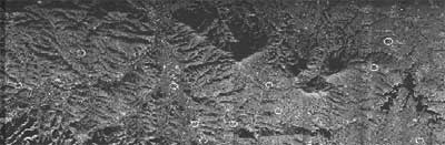
Fig.5 the target points’ distribution chart in the overlapping area of test data
The test accuracy can be testified with 1: 50000 relief graphics, under the condition of lacking 1:10000 ones. Additionally, the type of GPS installed on YUN-12 is Trimble-5700, with accuracy up to a cm, and INS system is LIN-92, with an accuracy: 0.5 degree (angle), 0.1 meter per second (line velocity).
4 DATA PROCESSING METHOD
According to the characteristic of the airborne SAR imaging in this test, we chose the following data processing.
4.1 Airborne SAR image data pre-processing
Because of the special imaging mode in this test, we must measure the different discrepancies between two adjacent image segments firstly, with which to transform the image coordinates into uniform image coordinates after we measured the image coordinates in the two image segments respectively. Additionally, some basal image processing is required, such as image radiation processing and so on.
4.2 DGPS data processing
In this test, the DGPS data are acquired with frequency of a 5Hz, and accuracy of plane 2.2 cm, height 4.8 cm. First, we measured the eccentricity weight from GPS antenna, which installed on the top of airplane, to the phase center of radar sensor. The result is the vector (2.15623, -0.45477, 2.15406). Then, we corrected the space position of imaging center of SAR sensor on flight from the DGPS data using matrix transform and eccentricity weight measurements. At the same time, the sparse GCPs used to correct the position of coordinates of radar sensor. To obtain the instantaneous position of imaging center corresponding a ground point P, it is necessary to adopt the interpolator computation, and, ultimately transform the WGS-84 coordinates to the ground coordinates we need through coordinates matrix transformation. In the test, the processing of DGPS data represented a strong turbulence in the practical flight mission, and the flight height results of the 11 target points along the flight course have a change of nearly 50m, which indirectly proved that the instability of flight status. And unlike the satellite-borne SAR sensor, this finally influenced the imaging quality, brought us added data processing burden.
4.3 INS data processing
The INS data are recorded with a frequency of 66Hz. And, what is most important is that the spatial and temporal calibration between the data records of DGPS and INS. In this test, we only extracted the INS data from the center of each airborne SAR image segment. With the navigation angle, we extracted out the three dimension coordinate weights of velocity vector, then, acquired the instantaneous coordinates against the ground target point by interpolator processing.
4.4 Multi-trajectory block adjustment
We adopted multi-trajectory block adjustment to realize the airborne SAR image triangulation. With the initialization of exterior orientation elements provided with DGPS and INS system, we using two or more flight trajectories, corresponding to the same area, to compute out the 3D ground coordinates for each ground target point.
4.5 First results
With our developed airborne SAR triangulation software, we obtained the first results of this test are not so satisfying. The best absolute accuracy of height is 21m, but the ones in X direction and in Y direction not all are reasonable, even the absolute error maximum is over several hundred meters, unfortunately. The partial reason is the processing of discontinuous imaging segments. The measure error derived from the SAR image coordinates increased with the diverse pixel displacements between two adjacent image segments along flight direction. Moreover, there is a lack of uniform imaging scale, so that it will bring us more problems in the farther processing. Even now, it has still verified the mathematical vector model and presented the potential of mapping application, and, with the improvement in imaging mode and application of better flight platform, it is still feasible that the airborne SAR image triangulation reduce the requirement of GCPs in some areas difficult to be mapped practically.
5 CONCLUSIONS
In this paper, the corresponding mathematical vector model and application test of high-resolution airborne SAR triangulation technique is introduced. Though the first results are not so satisfying, considering the practical flight conditions in this test, we still found the potential of airborne SAR triangulation technique to reduce the demand of GCPs supported by GPS and INS data, by sparse GCPs distributed around the test area, and realize dense GCP network of some areas difficult to be surveyed, or SAR imagery mosaic of large area.
REFERENCES
- Belgued Y., 1998. Application of radar triangulation to the calibration of interferometric DEM.IGARSS’98. 1998 IEEE international published: Vol.5, pp.2665-2667.
- Chang B. Y., Fang Y., 2002.The principles of positioning with space-borne SAR images. Geoscience and Remote Sensing Symposium,IGARSS '02. 2002 IEEE International, pp.1950-1952, June 2002, vol.4, pp.24-28.
- De Grandi G. F., Mayaux P., Simard M., Saatchi S., 2000. Fusion of the L-band GRFM and C-band CAMP wide area Central Africa radar mosaics: a new data set with unprecedented potential for regional scale vegetation mapping. Geoscience and Remote Sensing Symposium, Proceedings. IGARSS 2000. IEEE 2000 International, 24-28 July 2000, vol.1, pp. 4-6.
- Denise L., 1998. Application of radar space triangulation for 3D localization. European Conference on Synthetic Aperture Radar, 25-27 May 1998, Friedrichshafen, Germany, pp.351-354.
- Toutin Th., 2003. Path processing and block adjustment with RADARSAT-1 SAR images. IEEE Transactions on Geoscience & Remote Sensing, 41(10), pp. 2320-2328.
- Toutin Th., 1999. Error tracking of radargrammetric DEM from RADARSAT images. IEEE Transactions on Geoscience & Remote Sensing, 37(5), pp. 2227-2238.
- Toutin Th., 2003. Block bundle adjustment of IKONOS in-track images. International Journal of Remote Sensing, Feb., 24(4), pp. 851-857.