| GISdevelopment.net ---> AARS ---> ACRS 2004 ---> GPS & Photogrammetry: Digital Photogrammetry |
Finding True Position of
Buildings in Orthophotos
Liang-Chien Chen, Yi-Chung
Tung, Tee-Ann Teo
Center for Space and Remote Sensing Research
National Center University
Chung-Li, TAIWAN
Tel: +886-3-4227151 ext 7622, 7623 Fax: +886-3-4255535
TAIWAN
Email: lcchen@csrsr.ncu.edu.tw, 92322094@cc.ncu.edu.tw, ann@csrsr.ncu.edu.tw
Center for Space and Remote Sensing Research
National Center University
Chung-Li, TAIWAN
Tel: +886-3-4227151 ext 7622, 7623 Fax: +886-3-4255535
TAIWAN
Email: lcchen@csrsr.ncu.edu.tw, 92322094@cc.ncu.edu.tw, ann@csrsr.ncu.edu.tw
ABSTRACT
In order to acquire largest possible coverage for environmental monitoring, the overlapping area of satellite images is small in general. Hence, the traditional 3-D bundle adjustment may not be used for orientation modeling directly. We propose a revised bundle adjustment method that could overcome the weak geometry for tie points when a digital terrain model is available. The major works of the proposed schemes include: (1) transformation of work coordinate systems, and (2) bundle adjustment using DTM as an elevation control. Experimental results indicate that the proposed method may improve the relative accuracy for connecting images.
1. INTRODUCTION
High resolution satellites employ CCD linear array for image acquisition [Fritz, 1999]. Different from area sensors, the linear array sensors can not satisfy the demands of large coverage and stereoscopic observation at the same time. In reality, the major applications of the remote sensing images are the detection of natural resources and the monitoring for geoenvironment. In order to acquire largest possible coverage, the overlapping area of satellite images is small in general. Thus, the weak geometry of intersection will cause large elevation error. Hence, those tie points need elevation control in a bundle adjustment procedure. In this investigation, we propose a revised bundle adjustment procedure including DTMs (Digital Terrain Modals) as elevation control.
From the photogrammetric point of view, collinear condition equations are generally used in 3-D positioning for satellite stereo pairs. Based on the equations, a bundle adjustment may be performed to model the satellite orientation and the 3-D ground coordinates for the conjugate image points [Konecny et al., 1987; Gugan and Dowman, 1998]. According to the sampling geometry of satellites, the on-board orbital parameters and attitude data can be calibrated using a small number of GCPs [Chen and Chang, 1998]. The core of this investigation is performing a bundle adjustment using a DTM as surface control.
2. METHODOLOGY
The proposed method comprises two major parts. The first part is to define a Work Coordinate System for bundle adjustment. The second one is the bundle adjustment using DTM as an elevation control. Fig. 1 illustrates the work flow of bundle adjustment.
Fig.1. Work flow of bundle adjustment
2.1 Work Coordinate Systems
Before performing the bundle adjustment, we should transform all of the geometric parameters into a same coordinate system, including orientation parameters, GCPs, and tie points. Hence, we define a Work Coordinate Systems with coordinate direction of LVLH (Local Vertical Local Horizontal). The origin is set at the centroid of GCPs. We may, thus, avoid numerical instability and the projection error caused by a long track. In addition, the high correlation between orbit parameters and attitudes can be better depicted and separated in weighting [Chen and Teo, 2001].
2.2 Collinearity Condition
The collinearity condition equations state that the exposure station, any object points, and its image point all lie along a straight line. The equations are modified, as shown in Eq.1, to fit the imaging geometry of satellite images.
The exterior orientation parameters, including orbital and attitude, are characterized by second order polynomials as functions of sampling time t relative to the first scan line, i.e., as shown in Eq.2.
2.3 Bundle Adjustment
The purpose of the least squares adjustment in this investigation is to determine the most probable solution for the ground coordinates of all the unknown points and the exterior orientation parameters of all images [Wolf and Dewitt, 2000]. Besides the collinearity equations, exterior orientation parameters and object coordinate are included in the observation equations. We can correct exterior orientation parameters, ground coordinates of GCPs and tie points when a priori error is assumed. Then, we formulate weight of all parameters to distinguish the high correlation between location and attitude, and the difference between GCPs and tie points, as shown in Eq.3.
2.4 DTM Elevation Control
In order to overcome the weak geometry for tie points, we use DTM in the adjustment for elevation control. First, ray tracing technique is applied to determine the ground position of a tie point. The result locations of different orbits for the same tie points are not coincident. We take the average position of two ground points as the initial position of this tie point. Because the weak geometry of intersection exhibits elevation errors, we strive to use DTM recursively in the least squares adjustment. Referring to Fig. 2, the elevation “Z” without “prime” denotes the elevation after bundle adjustment, and the “Z” with “prime” denotes the elevation after interpolation in DTM. The subscripts of Z mean the number of iterations. The computation procedure starts from the initial value of Z1 to Z1’, then to Z2 and Z2’, and so forth until converged. In this way, we can control elevation error in a reasonable range that the convergence is expected. Fig. 3 illustrates the work flow of DTM elevation control.
Fig.2. DTM elevation control
Fig.3. Work Flow of DTM elevation control
3. EXPERIMENTS
In the experiments, we perform orbit adjustment for two strips. The experiments include two parts of validation. The first one is to examine the absolute accuracy. The second one is to evaluate the relative accuracy. The performance of the space resection and the bundle adjustment are compared.
3.1 Test Data
The test data include three strips of SPOT 5 panchromatic images. Those strips are with about 10% overlap. Related information of the test images is shown in Table1. The test area is in the middle part of Taiwan from west coast to east coast as shown in Fig 4. The ground control points and independent check points (ICPs) are acquired from 1:5000 scale photo basemap.
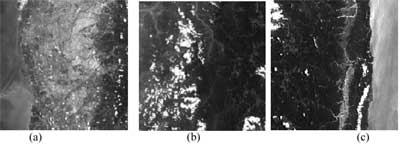
Fig.4. Test Image (a) Strip1 (b) Strip2 (c) Strip3
3.2 Absolute Accuracy Evaluation
There are two cases in this experiment. Case1 is the adjustments for strip1 and strip2. Case2 is the adjustments for strip2 and strip3. We evaluate the absolute accuracy by ICPs. Table2 and
Table3 illustrate the accuracy performance. In the space resection, the RMSE of ICPs is about 3~6m. In the bundle adjustment, the RMSE of ICPs is about 3~13m.
In this experiment, the absolute accuracy descends when tie points were used in the bundle adjustment, and the systematic errors emerge. It might be caused by errors of DTM and local systematic errors of orbit. Therefore, collocation technique would be needed for improving the absolute accuracy. In addition, small number of ICPs causing oscillate of RMSE might influence the results.
3.3 Relative Accuracy Evaluation
One pair of tie points will appear in two images, we thus check ground positions of tie point using check tie points (CTPs). Distance between these two ground positions is used to evaluate the orbit relative accuracy. Table4 illustrates the accuracy performance of tie points. Significant improvement of relative accuracy is demonstrated when tie points are employed in the adjustment.
4. CONCLUSIONS
This paper proposes a revised bundle adjustment procedure for multi-orbit satellite images. In the process of bundle adjustment, we use DTM as elevation control to overcome the weak geometry for tie points. Experimental results indicate that, bundle adjustment with DTM as elevation control can improve the relative accuracy between different strips. Further collocation technique should be considered for improving the absolute accuracy.
REFERENCES
- Chen, L.C., and Chang, L. Y., 1998, “Three Dimensional Positioning Using SPOT Stereostrips with Sparse Control”, Journal of Surveying, ASCE 124(2): pp.63-72.
- Chen, L.C., and Teo T. A., 2001, “Orbit Adjustment for EROS A1 High Resolution Satellite Images”, Proceeding of 22 nd Asian Conference on Remote Sensing, Singapore, pp1169-1174.
- Fritz, L. W., 1999, “High resolution commercial remote sensing satellites and spatial information system”. Highlight of ISPRS, vol.4, No. 2, pp.19-30
- Gugan, D. J., and Dowman, I. J., 1988, “Accuracy and completeness of topographic mapping from SPOT imagery.” Photogrammetric Record, 12(72), 787-796.
- Konecny, G., Kruck, E., Lohmann, P., and Engel, H., 1987, “Evaluation of SPOT imagery on analytical photogrammetric instruments.” Photogrammetric Engineering and Remote Sensing, vol. 53, no. 6, pp. 1223-1230.
- Wolf, P., & Dewitt, B., 2000, “Elements of Photogrammetry: with applications in GIS”, McGraw-Hill, 3rd edition, 608pages