| GISdevelopment.net ---> AARS ---> ACRS 2004 ---> GPS & Photogrammetry: Digital Photogrammetry |
Finding True Position of
Buildings in Orthophotos
Deeboon
Methakullachat
Assistant Professor, Faculty of Engineering
Kasetsart University
50 Phaholyothin Rd., Bangkok 10900
Tel: (662) 942-8555 Fax:(662) 579-4575
THAILAND
Email: fengdbm@ku.ac.th
Assistant Professor, Faculty of Engineering
Kasetsart University
50 Phaholyothin Rd., Bangkok 10900
Tel: (662) 942-8555 Fax:(662) 579-4575
THAILAND
Email: fengdbm@ku.ac.th
ABSTRACT
Orthophotos of urban areas do not always provide correct information of the position of buildings. Leaning buildings, caused by minor relief displacements, can be observed in orthophotos generated by the traditional method. Much research has been working on producing true orthophotos using digital surface model of a city. However the procedure is costly, time consuming and requires special software to handle the effects of occlusion. This is why orthophotos of urban areas generated by traditional method are still being produced in many places in the world. We thus encourage orthophoto map users to stay with traditional orthophotos for their good source of information. This paper describes a scheme that locates the correct position of buildings on a traditional orthophoto, by using exterior orientation parameters of the original photo. Building heights is another important piece of information and is extracted as part of the output results. A mathematic model is presented together with a numerical example of a least squares adjustment. Interestingly traditional orthophotos do store position as well as the height of buildings in one place while true orthophotos do not.
BACKGROUND
“A picture is worth a thousand words” is perhaps the best explanation of why orthophotos are so popular nowadays. Digital orthophotos can be displayed on a computer screen. They are lively, easy to understand, as precise as maps and, most importantly, carry more topographic information than any other sources.
Many people might think that to produce an orthophoto is not difficult, at least not as complicated as that of classical photogrammetry. However orthophoto generation of urban areas is somewhat sophisticated. In fact much research has been carried out to solve problems in orthophoto generation in cities (Amhar et. al., 1998, Schickler and Thorpe, 1998, Skarlatos, 1999, and Rau, et. al., 2002). The word “true orthophoto” was introduced and implies that there is a “false orthophoto” on the other side.
Regardless the methods that are used, true orthophoto generation cannot be possible without a digital surface model (DSM). The problem is DSM data may not be available. Moreover the procedure is costly, time consuming and requires special software. This subsequently force the production of orthophotos in many places in the world to use only the digital terrain model (DTM), which do not include height information of manmade objects. The resulting orthophotos are traditional orthophotos, better not use the word false orthophotos, in which leaning buildings maybe presented (see Figure 1).
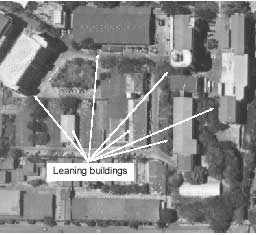
Figure 1 An orthophoto of Kasetsart University, showing some obvious leaning buildings
We know that the true shape and position of a building on an orthophoto are at the base. However, we cannot see all sides of the building at the base due to leaning buildings. Fortunately this is not the case for the rooftop. In classical photogrammetry, an experience operator knows that digitizing a rooftop of building is easier than digitizing at the base. The big question is, if we digitize the rooftop, where exactly the position of the building is.
THE RELIEF DISPLACEMENT
We begin with a character of the perspective projection that projects a point, having a different elevation, on a different position on a photograph. This is what we call “relief displacement”. There are two types of it, one is invisible and the other is not. The invisible relief displacement is due to terrain heights while the visible one is due to object heights (see Figure 2).
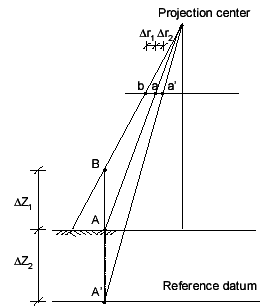
Figure 2 Visible relief displacement Dr1 and invisible relief displacement Dr2
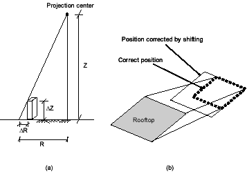
Figure 3 (a) Minor relief displacement (b) Simple constant coordinate shifting
During the process of orthophoto generation, relief distortions caused by terrain heights are removed using a DTM. However, due to lack of building heights in built up areas, relief displacement caused by building heights cannot be removed. The leftover relief is known as minor relief displacement (see Figure 3).
It should be mentioned that correcting a relief distortion is not just applying a constant shift to rooftop coordinates (see Figure 3b).
An approximated amount of minor relief displacement could be computed using Equation (1),
where DR is the minor relief displacement on an orthophoto, R is the distance from the building to the center of the photo, DZ is the building height and Z is the flying height above the terrain.
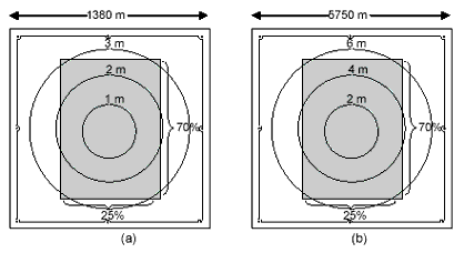
Figure 4 Minor relief displacement at scale (a) 1/6000 (f=300 mm) and (b) 125000 (f=152 mm)
Figure 4 shows contour lines having constant displacements caused by a 10 meters height. This is actually positioning errors when measuring at the rooftop of a building on an orthophoto. The shading area is the center portion of the photo used to generate an orthophoto.
CORRECTING MINOR RELIEF DISPLACEMENTS
Figure 5 (a) shows how a typical building is re-projected on an orthophoto. Due to lack of using a DSM, point A and B on the original photo do not fall at the same position on the orthophoto, hence minor relief displacement. On an orthophoto, point A is at the base and point B is at the rooftop. Let X0, Y0, Z0 be the exposure station coordinates, X1, Y1, Z1 be the coordinates of point A and X2, Y2, Z2 be the coordinates of point B.
For the sake of simplicity, point A and B are close enough and are assumed to have an equal elevation of zero. Z is the building height. Figure 5 (b) suggests that point A’, B and the projection center are on the same line. Therefore we can set up mathematic conditions to express the collinearity as follows.
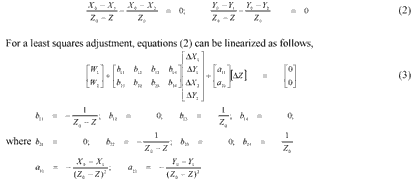
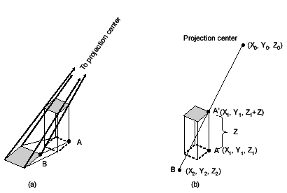
Figure 5 (a) Point A and B on a leaning building (b) Collinearity ofa light ray
and W1 and W2 are approximations of the mathematic model described by Equations (2). The adjustment model is known by the Gauss-Helmert model. Readers are invited to consult standard text books of adjustment computation for more details. Finally the true position of the building can be computed from Equation (4).
NUMERICAL EXAMPLE
A real world computational example is given here for a purpose of demonstration. A building was observed on an orthophoto with a significant minor relief displacement. Only one corner point of the building can be seen both at the top and the bottom. The coordinates measuring at the top and the bottom are (X = 494710.237, Y = 4251902.975) and (X = 494716.037, Y = 4251905.475) respectively. The projection center of the original photo has coordinates of (X = 495053.284, Y = 4252026.452, 538.977).
The shape of the building is rectangular and the other three corners whose coordinates measuring at the top are (X = 494695.137, Y = 4251953.47500), (X = 494710.837, Y = 4251951.17500) and (X = 494694.737, Y = 4251905.07500).
We start off with determining the height of the building by using least squares fitting. All observations are assumed to have an equal weight. The approximated height was set to zero. After the fourth iteration, having set a threshold at 0.0000001, the building height converts at 9.318 meters. The estimated standard deviation of unit weight is 0.277, yielding an accuracy of 0.573 meters for determined height.
Next we compute the corrected position of the building and the coordinates are (X = 494701.329, Y = 4251954.73671), (X = 494716.758, Y = 4251952.47648), (X = 494716.75812, Y = 4251952.47648) and (X = 494716.16850, Y = 4251905.10982). Please observe the last coordinates which are observations used to estimate the building height and got changed during the adjustment.
DISCUSSION
Collecting vector data is more likely to be done in a CAD system or a GIS. This is particularly true for two reasons. First photogrammetric workstations are expensive and costly to operate. Second digitization in 2D is faster. Here we propose a digitization scheme that will compute the true position of buildings. Many CAD systems and GIS have an ability to create external routines and be called when needed.
The proposed scheme assumes that the outer shapes of the building rooftops have equal heights. It begins by the user identifying a building with the relief displacement presents. The user then decides how he will estimate the building height. If the height can be directly measured, a least squares adjustment is performed, otherwise estimate by using other methods such as measuring on the nearby building. The system then uses the height information to compute the correct position of the building (see Figure 6).
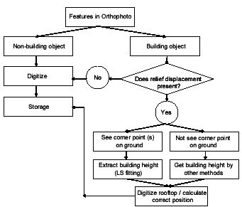
Figure 6 The Proposed scheme to digitize buildings on Orthophotos
CONCLUSIONS
There is no relief displacement in true orthophotos, hence no information about object heights. All objects in true orthophotos will appear to be flat. This is a disadvantage for the scenario may lead to interpretation problems. Here we conclude that traditional orthophotos do not fool our eyes as much as true orthophotos do. Moreover traditional orthophotos do store position as well as heights of buildings in one place while true orthophotos do not.
The bottom line is, rather than spending much effort on producing true orthophotos, map users should keep traditional orthophotos, keep the original terrain model, and spend effort on collecting true building position and heights.
Finally we would like to emphasize that coordinates of exposure stations of original aerial photos are important, for they relate minor relief displacements to object heights. Therefore they should be somehow attached to orthophotos. A mosaic orthophoto may have to find a way to deal with several sets of exposure station coordinates.
REFERENCES
- Amhar, F., Jansa, J. and Ries, C. (1998) The Generation of True Orthophotos Using a 3D Building Model in Conjunction with a Conventional DTM, International Archives of Photogrammetry and Remote Sensing, Vol. 32, pp. 16-22.
- Rau, J.Y., Chen, N.Y. and Chen, L.C. (2002) True Orthophoto Generation of Built-Up Areas Using Multi-View Images, Photogrammetric Engineering and Remote Sensing, Vol. 68, No. 6, pp. 581-588.
- Schickler, W. and Thorpe, A. (1998) Operational procedure for automatic true orthophoto generation. International Archives of Photogrammetry and Remote Sensing, Vol. 32, Part 4, pp. 527-532.
- Skarlatos, D. (1999) Orthophotograph Production in Urban Areas, Photogrammetric Record, Vol. 16, No. 94, pp. 643-650.