| GISdevelopment.net ---> AARS ---> ACRS 2004 ---> New Generation Sensors and Applications: Airborne Sensing |
Research for development of
small-format multi-spectral aerial photographing system named PKNU 3
Eun-Khung,
Lee
Master 2, Pukyong National University, Dept. of Satellite Information Sciences, KOREA,
Telephone: 051)620-6578,
Email: a4004@hanmail
Chul-Uong, Choi
Professor, Pukyong National University, Dept. of Satellite Information Sciences, KOREA,
Telephone: 051)620-6578
Email: cuchoi@pknu.ac.kr
Young-Chan, Seo
Master 2, Pukyong National University, Dept. of Satellite Information Sciences, KOREA,
Telephone: 051)620-6578,
Email: dromond@hanmail.net
Nam-Chun, Cho
Master 1, Pukyong National University, Dept. of Satellite Information Sciences, KOREA,
Telephone: 051)620-6578,
Email: pkphoto78@hotmail.com
Master 2, Pukyong National University, Dept. of Satellite Information Sciences, KOREA,
Telephone: 051)620-6578,
Email: a4004@hanmail
Chul-Uong, Choi
Professor, Pukyong National University, Dept. of Satellite Information Sciences, KOREA,
Telephone: 051)620-6578
Email: cuchoi@pknu.ac.kr
Young-Chan, Seo
Master 2, Pukyong National University, Dept. of Satellite Information Sciences, KOREA,
Telephone: 051)620-6578,
Email: dromond@hanmail.net
Nam-Chun, Cho
Master 1, Pukyong National University, Dept. of Satellite Information Sciences, KOREA,
Telephone: 051)620-6578,
Email: pkphoto78@hotmail.com
ABSTRACT
Originally, to allow for better flexibility in geological and environmental data collection, our laboratory developed the compact, multi-spectral automatic aerial photographic system called the PKNU2. This system's multi-spectral camera is capable of recording visible (RGB) and infrared (NIR) band (3032*2008 pixels) images. Visible and infrared band images were obtained from each of the two cameras of the PKNU2 respectively and produced color-infrared composite images to be analyzed for the purpose of the environmental monitoring. However, for the data this system provides, there is room for improvement. The PKNU2 also has the limitation of having the stereoscopic overlap area being 60% unsatisfied due to the 12 seconds of data storage time. However, a distinctive advantage of the PKNU2 system is its ability to photograph a high number of photos in a short time. Despite its limitations, PKNU2 system provides an excellent platform upon which an even better system may be built. The advanced PKNU2 system, designated the PKNU3, consists of a color-infrared spectral camera that can photograph in the visible and near-infrared bands simultaneously utilizing a single sensor, a thermal infrared camera, two computers of 120 gigabyte memory capacity to store images, and an MPEG board that can compress and transfer data to the computer in real-time as well as have the capability of utilizing a helicopter platform.
1. Introduction
The small-format aerial photographing system, designated the PKNU2, started development in June, 2001 and has completed its 6 th test on June, 2003 by the PE&RS Lab.(Remote Sensing Center) in Pukyong National University, Korea. This system was created for the purpose of obtaining useful data at low-cost along with high accuracy of spatial resolution at the target area in a timely manner for users. The Ortho photo map (planimetric accuracy: 0.78m, vertical accuracy: 0.83m) was produced as a test of the basic ability of PKNU2 to integrate with a GPS survey as well as to verify and calibrate the camera lens. A shortcoming existed that perfect R,G, B, and IR composite images could not be obtained because the RGB and infrared images were taken with separate cameras, requiring that the color-infrared composite images were to be produced in the post processing stage; although vertical photos with spatial-resolutions as high as 0.29m could be obtained using the PKNU 2. Thus, the objective of the PKNU3 was to enhance its Multi-spectral aerial photography capability while leaving the PKNU 2 to develop further into a high spatial-resolution photography platform.
This paper describes the development of the small-format multi-spectral aerial photography system designated the PKNU 3. The PKNU 3 is composed of 2 parts: a sensor portion con sisting of a spectral camera that capable of taking images of the R, G, B, and IR bands si multaneously as well as a thermal IR camera, and a data storage system (figure 1).
Figure 1 Multi-spectral aerial photographing system & platform
2. Application
2.1. Chronologic table of this study
This study was initiated on January 2004, and the field study, supported by the Ministry of Maritime Affairs & Fisheries and the Korea Environmental Institute, was completed with the 2 nd aerial photography test on September 2004. Objectives pertaining to each test are shown in the following table 1.
2.2. Multi-spectral aerial photographing system named PKNU 3
PKNU 3 consists of a sensor array, data storage system and platform as shown in figure 1. The sensor portion utilizes a REDLAKE MS 4000 multi-spectral camera and Raytheon IRPro thermal IR camera, both supports by gimbals to prevent the vibration of the platform and allow for adjustability of the photographic angle. The Data storage system is composed of an MPEG board, which can compress and transfer moving pictures in real time as high quality images, and two computers each with 120 Gigabyte memory capacities to store data in volume. The helicopter was chosen as the aerial platform because it could fly a low-speed and rotate 360 o thus making it able to fly in ways that fixed-wing aircraft are unable.
2.2.1. Sensor part
In the PKNU2 system had drawbacks in its ability to obtain composite 4-band images of any particular target area because the task of photographing the color and near infrared images was divided between the separate Kodak DCS 460 color and infrared cameras respectively. In addition, it was difficult to control the least overlapping rate (60%) due to the 12-second interval of storage. Therefore, the REDLAKE MS 4000 sensor was introduced to overcome this drawback as well as provide the capability of obtaining moving picture data.
The REDLAKE MS 4000 sensor is a triple CCD camera that can take R, G, B, and IR band images simultaneously so it can produce RGB and CIR images of the target area of 1600 ×1200 pixels (7.4 . per pixel). The light sensitivity of the camera lens is controllable using gain values and an electronic shutter. The thermal infrared camera, a Raytheon IRPro, used in this study, senses the energy of the 7~14 . wavelength as still and moving pictures and displays through an LCD viewer. Distribution of thermal energy in images can be displayed through the use of 5 colors (red, orange, yellow, green, and blue) and temperatures be shown in terms of brightness values. These two cameras (REDLAKE MS 4000 & Raytheon IRPro) are mounted on gimbals specially designed to prevent platform vibration as well as provide a wide adjustability of the photography angle. While the MS4000 has automatic focus ability, the thermal IR camera does not; therefore, a separate unit to remotely control the thermal IR camera's focus was added to the gimbals/camera assembly.
2.2.2. Data Storage system
A high capacity data storage system is necessary record the volumes of images due to the 1 second data storage time of MS 4000. Two compact computers of 120 Gigabyte storage capacities with a 12-volt power supply were implemented for the data storage system because the PKNU 3 depends on onboard power of the aerial platform. The two computers are tightly packaged in a special case that insulates from the vibration energy of the helicopter platform. To further reduce vibration, a wiring harness was implemented that consolidates every connector between the sensor components and the data storage system as one thick cable.
2.2.3. GPS
A GPS antenna was included with PKNU 3 to compute the flight course, flight velocity, and altitude of aerial platform as well as provide 3 dimensional coordinates of each exposure station (x, y, z), and rotation angle of platform , . , K ) for exterior orientation.
2.3. The 1 st aerial photographing test
The 1 st test was an evaluation of PKNU 3's essential capabilities. An aerial platform (helicopter) equipped with the PKNU 3 left the Air Force Base inside of Kimhae Airport 24 minutes, 27 seconds past 2 PM and completed its flight plan 48 minutes, 47 seconds past 3 PM on September 9, 2004.
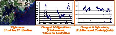
Figure 2 1st flight course, altitude and velocity
According to the analysis of recorded GPS data, the altitude of the 1 st flight was approximately between the minimum MSL (Mean Sea Level) of 100m to a maximum of 450m with a maximum flying speed of 200km/h. From this test, we are unable to provide exterior orientation using GPS data due to an operating mistake of the GPS receiver; it was erroneously set at a 20s interval of data acquisition instead of the specified 1 second interval.
Pictures taken at the 1 st test were underexposed due to cloudy and rainy weather and a lack of radiation intensity. Many images were out of focus because of a miscalculation of an a ppropriate exposure time with helicopter speed going faster than the anticipated 100km/h. Moreover, it was difficult to maintain the proper balance among R, G, B, IR band sensitivi ty in each CCD sensor as a lack of intensity of radiation made gain value control difficult.
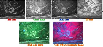
Figure 3 Steel photographs (4-band)
As the result of the 1st test, 4-band steel pictures of BSQ format were 278sheets ( ´ 7510 Kb = 1.96 GB), 72 minutes of moving color pictures (722 Mb) and 2.4 GB of moving thermal infrared pictures were obtained.
2.4. The 2 nd aerial photographing test
The 2 nd test was an evaluation of the PKNU 3's capability of providing multi-spectral photographing in volume. The 2nd flight was started at 19 minutes, 40 seconds before 2 PM on the airfield of the Dalmaji Hill, Haeundae, Busan and finished 25 minutes, 30 seconds past 3 PM in the same area after flying over Geojedo, Tongyoung, Gaduckdo, and the Daebyun port. According to the analysis of GPS receiving data, flight altitude was kept between 100m to 400m and flying speed was maintained between 100 ~ 220 km/h as shown in figure 4.
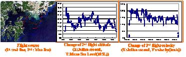
Figure 4 2nd flight course, altitude and velocity
PKNU 3 took 6200 sheets ( ´ 7510Kb=46.56 GB) of still pictures, 108minutes of moving color pictures (4.16 GB), and 4.3 GB of moving thermal infrared pictures during the 1 hour 45 minute duration of the 2 nd flight. Photographic area per sheet of image was 0.022 2 km (0.17km ´ 0.13km) and the spatial resolution was 0.11m due to the low altitude.
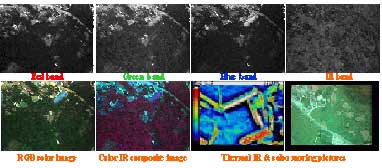
Figure 5 Results of the 2nd flight
Figure 2 Steel photographs (4-band) & RGB, CIR images & thermal IR, color moving pictures Images with overlapping rate of 60~70% were able to be obtained by storing each data with 1s interval automatically. The attributions of sensor including the coordinates and rotation values of platform at each exposure station, and gain values and exposure time for each band to control electronically the reaction of coming light through lens are as following table 2.
2.5. Application of results
Images resulted from this study will be applied to various fields as shown in table 3.
3. Conclusion
As of September 2004, the PKNU 3 development schedule has reached 2 nd testing phase. Various experiments and tasks for the improvement of this system were conducted and following has been achieved:
Firstly, a Multi-Spectral aerial photography system has been created that, at its core, consists of a sensor that can take R, G, B, and IR images simultaneously to immediately produce a composite RGB and CIR image of a target area, coupled, with a thermal infrared sensor. Second, with an integrated Data Storage System, high volume photography from long distance flights as well as the ability to obtain images with an overlapping rate of 60~70% using an automatic 1 second interval data record time are now possible.
Third, the Thermal IR sensor's lack of self-focusing ability has been mitigated by the successful implementation of a remote focus-control system that is installed in the gimbals/camera assembly.
Forth, it was determined that images were out of focus due to a miscalculation of appropriate exposure time (lack of synchronization between aerial platform velocity and exposure calculations), and the difficulty in maintaining proper balance among R, G, B, IR band sensitivity in each CCD sensor with inaccurate gain values from the low intensity of radiation during the 1 st flight.
Fifth, determination of appropriate exposure time and gain values during the 2 nd test was successfully completed and the coordinates and rotation values of the platform at each exposure station were able to be computed from processed GPS data. It was possible to make a strip of images automatically using these factors of exterior as well as interior orientation (focal length, value of lens distortion correction, corrected principal point).
Continued study is warranted for enhancing the system with the use of gyroscopic and IMU units in addition to verifying data and calibration procedures of the system.
4. Acknowledgements
We express our gratitude to the Pukyong National University, the Ministry of Maritime Affairs & Fisheries, and the Korea Environmental Institute for their support of this study.
5. References
- Cramer, M., Stallmann, D. and Haala, N., 2000. Direct Georereferencing Using GPS/Inertial Exterior Orientations for Photogrammetric Applications, IAPRS Vol. XXXIII Part B3/1, pp.198-206.
- Livingstone, D., Raper, J. and McCarthy, T., 1999. Integrating aerial videography and digital photography with terrain modeling, Geomorphology 29, pp. 77-92.
- Ron Graham and Alexander Koh, 2002, Digital Aerial Survey Theory and Practice. Whittles Publishing. pp. 52-121.
- Paul R. Wolf, 1983, Elements of Photogrammetry Second Edition, McGraw-Hill, pp576-614.
- Roger Read and Ron Graham, 2002, Manual of Aerial Survey Primary Data Acquisition, Whittles Publishing, pp.33-71.