| GISdevelopment.net ---> AARS ---> ACRS 2004 ---> New Generation Sensors and Applications: Line Scanner |
Measurement of Landslide
Displacement by object extration with ground based Portable Lased
Scanner
Kouji UJIKE and Msataka
TAKAGI
Kochi University of Technology
Tosayamada-cho, Kochi, 782-8502, Japan
Email: 075013b@gs.kochi-tech.ac.jp
Kochi University of Technology
Tosayamada-cho, Kochi, 782-8502, Japan
Email: 075013b@gs.kochi-tech.ac.jp
ABSTRACT
Landslide is a phenomenon of mass slowly movement in very wide area. Currently, it is difficult to measure whole landslide area using existing landside displacement monitoring systems. Because landslide displacement monitoring systems can measure at some points or along lines. The ground based portable Laser Scanner has some advantages; wide area and high resolution data can be obtained in a short time. Therefore, the ground based portable Laser Scanner may be useful for landslide monitoring. However, portable Laser Scanner has a problem for highly accurate measurement. Because, Laser Scanner does not have telescope for collimation, then it is difficult to measure same points in each observation. To solve the problem, the extraction of three dimensional objects from laser scanning data will be necessary to detect landslide displacement. In this study, the method for measurement of landslide displacement by object extraction with ground based portable Laser Scanner was discussed. For object extraction, training data which were three dimensional object model by CAD will be compared with laser scanning data. High accurate location of the training data were calculated by finding nearest distances between Laser Scanner data and each surface of object model. After that, landslide displacement will be detected by using time series data which extracted object. The object extraction showed reliable result for monitoring landslide by comparing with survey data using Total Station.
1. INTRODUCTION
Currently, Laser Scanner is expected in many fields. Because, it can acquire three-dimensional data in a short time, in wide area. Therefore, Laser Scanner can be used for a disaster prevention or 3D topographic surveying in high resolution. In case of measuring movement phenomenon like landslide must be compared with same points in time series data. However, measurement using Laser Scanner is difficult to compare same points in each observation, because Laser Scanner has not telescope for collimation.
2. OBJECTIVES
In this study, a method for 3D object extraction was developed. The location and attitude of extracted objects can be compared accurately in time series. Developed method was applied to monitor landslide displacement.
3. TEST AREA
In Shikoku, Japan, four big active faults exist. Many landslide is occurred along the active fault. Now, landslide prevention areas exist over 1,500 places in Shikoku, Japan. In this study, test area was selected Chouja landslide, Shikoku, Japan. In Chouja, width of landslide is about 200m, length is about 900m and average slope is about 15 degrees. It is one of the biggest landslides in Japan. As Observation site, shore-protection blocks was selected (Figure 1). Because they are located in the end of landslide area where has big movement.
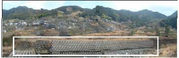
Figure 1: Observation area
4. LASER SCANNER
In this study, ground based portable Laser Scanner (RIEGL Japan. Ltd.) was used. It is a kind of electro-optical distance meter without prism. Maximum measurement range is 350m. Accuracy is about 0.025m in standard deviation. Measurement principle was the same as a Total Station. Table 1 showed specification of Laser Scanner. Figure 2 showed image of Laser Scanner.
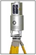
Figure 2: LMZ-210
5. METHOD OF MEASURING LANDSLIDE DISPLACEMENT USING OBJECT EXTRACTION
Figure 3 showed flow chart of the method. Firstly, object model was generated. It was compared Laser Scanner data. Then location and attitude of object model was adjusted. Finally, landslide displacement will be detected.
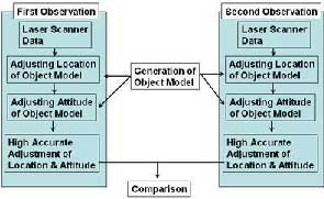
Figure 3: Flow chart of method
5-1. Generation of Object Model
One of shore-protection blocks (Figure 4) was measured by using a tape measure. Next, three-dimensional object model (Figure 5) was generated by CAD. This model was used for extracting objects from Laser Scanner. In this study, surface ~were used for matching with Laser Scanner data.
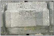
Figure 4: Selected object
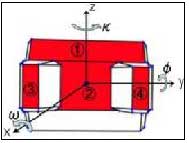
Figure 5: Object model
5-2. Adjusting Location of Object Model
Location of the object model was calculated as follows;
- Selecting center of the surface in Figure 5 by visual interpretation of Laser Scanner data.
- Extracting 20 points around the center.
- Establishing following equation of the surface from extracted points
by least square method.
- aX + bY+ cZ = 1 ······· · Eq.1
X, Y, Z : Ground coordinates of Laser Scanner
a, b, c : Coefficients - To calculate distance from each point of Laser Scanner data to the surface .
- When the distance showed within 0.05m, the points are extracted moreover for calculating accurate location.
- The accurate location (Xg, Yg, Zg) of object was calculated average coordinate of extracted points.
- Primacy attitude , f , . ) of object was calculated by following equation using coefficients (a,b,c) of equation of surface.
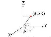
Figure 6: calculation method of angle
5-3. Adjusting Attitude of Object Model
Firstly, Laser Scanner data was judged inside or outside of each surface by using equations of rectangle surface model. The surface model could be expressed by two vectors of the base and height. Following equations show rectangle surface model by parameter type.
When parameters satisfied following condition in two dimensional plane, the point can judged inside of the rectangle surface.
Moreover, the points were extracted as consisted point of surface when distance between surface and the point existed within 0.05m. Next, accurate attitude , .f , .. ) can be calculated as follows;
- Calculation of rotation around X axis ).
- Points of Laser Scanner including surface were used.
- Rotation angle could be calculated by a regression analysis in Y-Z plane (Fig7a).
- Calculation of rotation around Y axis ().
- Points of Laser Scanner including surface were used.
- Rotation angle could be calculated by a regression analysis in X-Z plane (Fig7b).
- Calculation of rotation around Z axis ().
- Points of Laser Scanner including surface and were used.
- Rotation angle could be calculated by a regression analysis in X-Y plane (Fig7c).
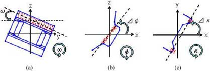
Figure 7: Calculation principal of matching for adjusting attitude
5-4. Comparing object model
6. RESULT
Figure 8 showed extracted objects. In this study, totally 42 objects were extracted. Observation date of Laser Scanner data was 16 March 2004 and 11 July 2004.For validating object extraction, three reflectors were pasted on the surface of the object.
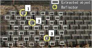
Figure 8: Object extraction place
The reflectors observed location of the object accurately by Total Station. 6-1. Result of location in object extraction Figure 9 showed displacement of location (Xg,Yg,Zg). In this figure, the displacement ranged from 0.02m to 0.15m. And big displacements were located on upper side.
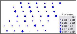
Figure 9: Comparison center of gravity
Table 2 showed result of displacement by object extraction in three objects where reflectors were pasted. Table 3 showed result of displacement by Total Station. The difference between object extraction and validation data showed about 0.05m.
6-2. Result of attitude , ö , ê ) in object extraction
Figure10-12 showed displacement of attitude , ö , ê ). Figure 10 showed displacement of attitude ù . In this figure, the displacement ranged from 0.014°to 4.32°.
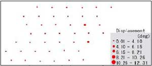
Figure 10: Displacement of attitude
Figure 11 showed displacement of attitude f . In this figure, the displacement ranged from 0.01°to 10.48°.
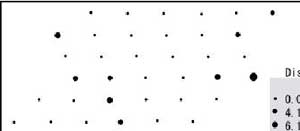
Figure 11: Displacement of attitude
Figure 11 showed displacement of attitude . . In this figure, the displacement ranged from 0.117°to 12.308°.
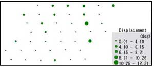
Figure 12: Displacement of attitude
In each displacement of attitude ,,) has no tendency in observation area.
7. CONCLUSIONS
Object extraction for detecting displacement was success to develop. The accuracy of object extraction showed 0.05m by comparing only three validation data. More number of validation data were required to evaluate the object extraction. At least 0.1m displacement will be detected by this method. In the observation period, big displacement did not occurred in test area. Measurement using Laser Scanner must be continued until success to detect landslide displacement.
8. REFERENCE
- Misao Mituoka, .Three-dimensional Modeling for Landslide Displacement Monitoring by Laser Scanner ., Graduate student, Kochi University of Technology, master thesis, 2003
- RIEGL Japan. Ltd., .LMS-Z210 owner's manual .
- Kochi pref., .Report of Choujya landslide ., 1994