| GISdevelopment.net ---> AARS ---> ACRS 2004 ---> Data Processing: DEM/3D Generation |
SPOT 5 Builds a Global
Multi-Purpose 3D Database: Reference3D
F. Axes, M.
Bernard
pot Image,
5 rue des Satellites - BP 4359 - F31030 Toulouse Cedex 4 – France –
E-mail: francoise.axes@spotimage.fr, marc.bernard@spotimage.fr
pot Image,
5 rue des Satellites - BP 4359 - F31030 Toulouse Cedex 4 – France –
E-mail: francoise.axes@spotimage.fr, marc.bernard@spotimage.fr
ABSTRACT
The successful launch of the SPOT 5 satellite on May 3rd, 2002 can be seen as a milestone for DEM and 3D daases, because its payload includes HRS, a stereoscopic imaging instrument which collects large strips of stereo data (120 by 600 km). After 2 years in orbit, HRS has acquired more than 70 millions km² of cloud free data, which is progressively processed into a 3D daase named Reference3D.
Reference3D includes a DTED level 2 DEM and an imagemap, secured by exhaustive quality and insurance procedures. It opens an easy and affordable access to qualified and homogenous elevation data over large areas, exactly the kind of very useful data (“basemap”) which procurement was highly problematic in the past.
The paper briefly describes the HRS sensor on-board SPOT 5, and then presents the quality insurance procedures that guaranty the meeting of ambitious requirements, and the accuracy assessments performed by independent labs (ISPRS, NGA, …)
Finally, the paper shows some of the various applications of such homogenous and large-coverage daase, focusing on middle-scale mapping.
1. INTRODUCTION
SPOT5, the fifth satellite of the SPOT remote sensing satellite family was successfully launched on the 4th of May 2002. SPOT5 ensures continuity of data acquisition and space image services but also to provides users with advanced products. It flies two identical cameras named HRG (High Resolution Geometry) providing a 2.5 m and a 5 m resolution in a panchromatic mode and a 10 m resolution in a multi-spectral mode, still keeping a 60-km ground field. Stereo application complements SPOT5 mission ; the satellite flies a specific High Resolution Stereo instrument (HRS) made up of two telescopes allowing a 20° fore view and a 20° aft view over a 120-km swath, sampling the landscape every 5m. HRS was designed to build up a worldwide digital elevation daase called Reference3D covering 30 to 50 millions km², one third of the globe’s landmasses, in five years. Its remarkable ability to acquire stereopairs is a huge step forward not only for production of high-quality digital elevation models (DEMs) to map relief, but also for automatic production of orthoimages of unrivalled geometric accuracy. Reference3D is the result of a dual-use civil/military programme designed to very strict specifications.
2. HRS SENSOR ON-BOARD SPOT 5
The HRS instrument is made of two telescopes allowing a 20° fore view and a 20° aft view over a 120-km swath, respectively (Figure 1). This concept of along-track stereo view enables both panchromatic pair images to be obtained within an interval of a 90 seconds for each pixel line in a single pass (Figure 2). This is a major advantage which ensures maximum correlation between the two stereopairs images since the time interval is the chief obstacle when generating a DEM (due to the changes of landscape). The resulting B/H ratio is slightly higher than 0.8. Each telescope has a 580 mm focal length and a focal plane made of 12000 detectors, size 6.5µm. The instantaneous field of view is 10 m but the sampling rate is 5 m along the track allowing higher altimetric precision of the DEM (Digital Elevation Models) to be obtained (in-flight calibration assessment was 4m rms). As fore and aft image acquisition operations are exclusive, the length of a continuous stereo segment cannot exceed 600 km. However several segments can be processed together for mass production.
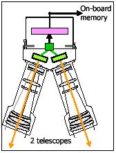
Figure 1 : HRS camera
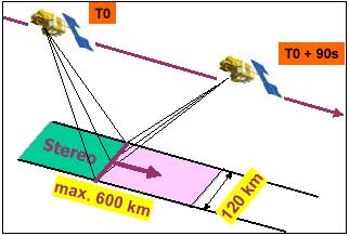
Figure 2 : The acquisition process of HRS stereopairs
The accurate on-board determination of the satellite position (1m rms) and the absolute dating are supplied by DORIS. Both gyroscopes and a star tracker provide the attitude of the satellite. This information is sent with the HRG and HRS instruments telemetry for further precise geometric processing on ground : 35m location accuracy for HRG and 25m for HRS without any ground control point. The SPOT 5 satellite is steered around the yaw axis so as to balance the earth rotation and both optimize the overlap between the stereo images taken by HRS and ensure that the shift between the 2 images taken in very high resolution (VHR) mode is exactly 0.5 pixels across the track (Gleyzes, 2003).
3. THE REFERENCE3D DAASE
This great capacity for stereo acquisition is combined with an industrial production line developed by Spot Image and the IGN (Institut Géographique National, France) to make a worldwide altimetry data base, Reference3D, which will cover more than 30 million km² over a 5 year period.
3.1 Reference3D daase
Reference3D is made up of 3 information layers (Bernard M., 2004).
3.1.1 Reference3D DEM: This file contains a uniform grid of terrain elevation values of an area of interest and is obtained through automatic correlation of SPOT HRS stereopairs. Its characteristics are the following :
- DTED level 2 format,
- fixed latitude spacing : 1 second of arc, about 30 m at the equator, varying according to latitude,
- variable longitude spacing: 1 second of arc up to 50° latitude, 2 seconds of arc from 50° to 70°, etc…
- Absolute horizontal accuracy (CE 90): =15 m
- Relative horizontal accuracy (CE 90): =10 m
- Vertical accuracy (Table 1)
Table 1 : Vertical accuracy according to the slope 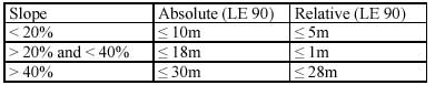
- Coverage with one degree square tile is guaranteed 100% (any posting is given an elevation) ; with at least 90% of the elevation values derived from HRS data
- DEM values are given in geographic coordinates with respect to WGS84. The vertical datum is EGM 96.
- fixed latitude spacing : 1/6 second of arc, about 5 m at the equator,
- variable longitude spacing: 1/6 second of arc up to 50° latitude, 1/3 second of arc from 50° to 70°, etc…
- Absolute horizontal accuracy (CE 90) : 16 m
- Over one degree square tile the residual cloud cover is under 10%
- Orthoimages are provided in geographic coordinates with respect to WGS84.
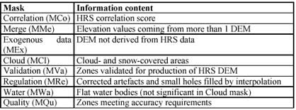
All masks are one-bit files that register perfectly with the DEM (post spacing is the same and values are expressed as geographic coordinates).
Reference3D comes in geographic tiles of 1°x 1° covering emerged land areas and aligned along parallels and meridians. The surface area of a tile, equivalent to 111 km x 111 km at the equator, decreases as the latitude increases. Reference3D comes in a DIMAP format. The HRS DEM is 100% compliant with the level 2 DTED format.
3.2 Reference3D production line
Specific resources have been devoted to Reference3D validation, completion and management, both in IGN and Spot Image, through a strategic operational partnership. The production line is quite automated.
The first step is the qualification of the HRS archive. As soon as received from the satellite, each and every HRS stereo strip is qualified by IGN teams, to check whether the data is able to provide DEM over the whole strip. Invalidated areas (clouds, haze, smoke, snow,…) are reported to the Spot Image tasking unit, which makes the appropriate decision : either tasking HRS again over the missing zones, or find any other source to fill the gaps. The HRS validated stereo-pairs worldwide coverage is more than 70 millions km² on the 20 th of September 2004.
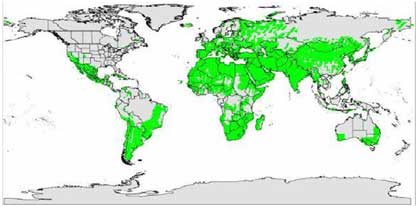
Figure 1 : HRS validated coverage map September 20th, 2004 70 585 275 km² or 27,027 million sq. miles
The production process starts once the HRS archive has been validated on a block area. The data are generally processed by working units of 5 to 12 HRS stereo strips.
The next step consists in the geometric positioning of the HRS stereo strips via a block-adjustment process, running over large areas ( ± 500 000 km²). The qualified strips are pre-processed in order to take into account the ephemeris data, tie points within each HRS stereo pair, tie points between HRS and HRG images in case of tri-stereo adjustment, distribution of HRS stereo pairs into triangulation blocks. HRS stereo strips are then jointly triangulated through iterations to reach the ultimate accuracy. There is no need of ground control points. DEMs are extracted by automatic correlation per HRS data strip, at 30m resolution. The 5 to 12 DEMs (and correlation coefficients) strips are first assembled, corrected from biases between adjoining data strips, and divided into geographic tiles of 1°x 1°. Post-processing steps include large water bodies identification, calculation of a uniform altitude within the water bodies, correction of artefacts and small holes by interpolation, correction of gaps superior to 10 km² with exogenous data (SPOT, ASTER, SRTM, GTOPO30). The last steps are the calculation of the 5m resolution orthoimage from the HRS aft view, the cutting into a file corresponding to the Reference3D frame, and the generation of the final Reference3D product in Dimap format. Metadata are registered along the production line.
Once precisely located, the HRS DEM and orthorectified image data are generated and integrated into the Reference3D server, along with detailed quality information.
3.3 Quality insurance procedures
Spot Image is the first European supplier of satellite data to have been awarded ISO 9001:2000 certification. This includes the design, production and sales of geographic information products, systems and services based on satellite data and is a guarantee of high quality services. The quality control of Reference3D is made according to a global quality program which includes the following main steps.
First, the coverage and quality of HRS are controlled internally by Spot Image with a specific tool (a minimum of 98% of the area must be correlated by the tool), and then IGN (through the analysis of the matching scores).
Second, the block-triangulation only starts once the HRS stereo strips have been validated. The quality control is based on the analysis of residuals from the block-adjustment process calculated on the tie points. Validation certificates are emitted by IGN after such control. Third, the controls are done all along the production steps and registered on a detailed form : correction of biases and artifacts, mosaic of DEM and masks, overlay of water bodies over the DEM, quality of the DEM (control of the content, statistics on altitude values, control of mosaic), quality of the final orthoimage, format control with the generation of a certification report, visualization of the three Reference3D layers with an internet browser.
As a fourth step, a person outside the production team makes consistency controls (between DEM, orthoimage and all metadata) on the final delivery media (CD-Rom).
As a fifth step, Spot Image controls three parameters on the CD-Rom delivered by IGN : format control (double check with IGN’s one), correct opening of the files and visual control of DEM and orthoimage, control of masks on a subset of the delivered products. The Reference3D tiles are finally archived in three copies in Spot Image and IGN (Toulouse and Paris).
4. ACCURACY ASSESMENT OF REFERENCE3D
The production process employs a model that retains overall geometric consistency and homogeneity over large areas. The inherent geometric precision of HRS data, combined with the Reference3D production process, yields higher levels of accuracy than ever before - 15 m CE 90 horizontal and 10 m LE 90 elevation - without any need for GCPs. The HRS DEM of Reference3D complies with the specifications for the level 2 DTED accuracy.
The International Society for Photogrammetry and Remote Sensing launched in 2002 a “Study Team” to assess HRS accuracy. More than twenty laboratories worldwide presented their results at the ISPRS congress in July 2004 in Istambul (Toutin, 2004; Reinartz, 2004; Kornus, 2004). The latest assessments gave a “4 to 5m” vertical accuracy. Other independent evaluations of Reference3D products are going on, including DGIA’s.
5. REFERENCE3D APPLICATIONS
The ability of SPOT 5’s HRS instrument to acquire large area stereopair images, combined with Spot Image’s and IGN’s industrial production facilities, makes it possible to build up Reference3D coverage at a rate of seven million square kilometres every year. As a result, users can be sure to find suitable Reference3D data for areas of interest as small as a single degree-square tile or as large as an entire country. Reference3D will be a key player for low-cost orthoimage production, because it will provide a geometric reference to register any image from SPOT 1 to 5, as well as from other sensors. In other words, HRS will help users to get rid of control points, thus saving a great deal of time, effort and cost, though they will probably not even suspect the HRS benefit for their 2.5m or 5m SPOT 5 HRG orthoimage.
Spot Image launched in December 2003 the development of an instant automatic orthorectification shop called ANDORRE. It has been designed to support automatic production of SPOT orthoimages and DEMs, in order to reduce orthoimagery costs and lead times. Because data are tied to the single reference system Reference3D, ANDORRE offers temporally and spatially uniform products covering large areas with an exceptional accuracy. It needs no extra personnel or mapping specialists to operate in routine configuration, but users can work in manual mode for greater control over the production process or to check product quality. Results obtained so far indicate that ANDORRE takes less than 2 hours to produce automatically a 2.5- m colour, full-scene SPOT orthoimage (60 by 60 km). This tool, which will be operational at Spot Image by end 2004, will also be marketed and sold to receiving stations with a SPOT 5 Terminal and to any organization with a Reference3D database required to orthorectify imagery. Reference3D also serves a broad spectrum of applications, since all GIS products on the market today use aerial or satellite imagery to varying degrees. These images must register accurately with other data layers, from statistical, documentary, administrative, socio-economic, geographic and other sources. Corrections for relief displacement, essential for the registration, will be accurate enough outside densely populated urban areas.
Mobile phone network planning is currently one area where 3-D data are greatly in demand, but DEMs are also widely used in agriculture, for environmental impact studies and by government mapping agencies. Mapping agencies and Defense ministries are among the biggest users of orthoimagery, which provides vital information for maps production of updating, checking existing database, aerial mission planners, weapon and command information systems. Combined with DEMs, orthoimages give a detailed picture of terrain relief in future theatres of operations. Consequently, they have become a key asset for low-altitude flight simulations. HRS is thus set to meet a range of as yet unfulfilled requirements, while improving quality and cutting lead times.
REFERENCES
- Bernard M., 2004. Reference3D Product Description. http://www.spotimage.fr Gleyzes J.P., Meygret A., Fratter C., Panem C., Baillarin S., Valorge C., 2003. SPOT5 : System overview and image ground segment. In: IGARSS proceedings, Toulouse, 2003.
- Kornus W., Alamús R., Ruiz A., Talaya J., 2004. Assesment of DEM accuracy derived from SPOT5 high resolution stereoscopic imagery. In: International Archives of the Photogrammetry, Remote Sensing and Spatial Information, Istambul, Vol.XXXV, Part B1.
- Müller R., Reinartz P., Lehner M., Schroeder M., 2004. Comparison of the accuracy of DEM from SPOT HRS two-fold stereo data and HRS/HRG three-fold stereo data in Barcelona Test site. In: International Archives of the Photogrammetry, Remote Sensing and Spatial Information, Istambul, Vol.XXXV, Part B1.
- Reinartz P., Lehner M., Müller R., Schroeder M., 2004. Accuracy analysis for DEM and orthoimages derived from SPOT HRS stereo data without using GCP. In: International Archives of the Photogrammetry, Remote Sensing and Spatial Information, Istambul, Vol.XXXV, Part B1.
- Toutin T., Briand P., Chénierc R., 2004. DTM generation from SPOT HRS in-track stereo images. In: International Archives of the Photogrammetry, Remote Sensing and Spatial Information, Istambul, Vol.XXXV, Part B1.