| GISdevelopment.net ---> AARS ---> ACRS 2004 ---> Data Processing: DEM/3D Generation |
Automatic Flight Planning for
Unmanned Aerial Vehicle Utilizing GIS Analysis on Digital Elevation
Model
Itthi Trisirisatayawong,
Pannee Cheewinsiriwat
Geo-Image Technology Research Unit, Dept. of Survey Engineering
Chulalongkorn University, Bangkok 10330, Thailand
Tel: +66 (0)-2218-6654 Fax: +66 (0)-2218-6653
E-mail: itthi.t@eng.chula.ac.th, pannee.ch@chula.ac.th
Geo-Image Technology Research Unit, Dept. of Survey Engineering
Chulalongkorn University, Bangkok 10330, Thailand
Tel: +66 (0)-2218-6654 Fax: +66 (0)-2218-6653
E-mail: itthi.t@eng.chula.ac.th, pannee.ch@chula.ac.th
ABSTRACT
This paper describes a GIS-based application to plan image-acquisition mission of unmanned aerial vehicle (UAV). Short range UAVs of up to 200 km operational distance are being developed by various universities and the army’s artillery division under a joint research funded by the Thailand Research Fund and the Ministry of Defence. The ultimate goal of UAV is to fly to take images of target areas, particularly those along or over the border, using onboard video camera. The acquired images will be mainly used for security purposes such as surveillance, reconnaissance, military mapping or intelligence. The nature of this task is always risky. Though UAVs require no human pilot aboard and thus incur no human loss, any loss of the aircraft is still considerable. Avoiding such loss by flying UAVs further away from the target area, the imaging mission may fail. Optimum flight path is therefore critically important to the success of UAV mission. Flight parameters including altitude, aircraft position, look-angle and time must be thoroughly and carefully pre-determined to ensure that the desired image will be taken while aircraft safety is maintained. The computation of UAV positions and the image acquisition time must also take into the account problems such as line-of-sight obstruction or hill shadow. As part of the UAV research project, a software module for automatic flight planning has been developed in a GIS environment to analyse digital elevation mode (DEM), sun angle and azimuth, the aircraft capabilities and limitations in order to produce optimum flight parameters. Logical block diagrams, procedures and results are detailed in the paper.
1. INTRODUCTION
Unmanned aerial vehicles (UAVs) are remotely piloted or self-piloted aircraft that carry communication equipments and cameras, sensors, or other payloads. The advantages offered by UAVs to civilian and military users are numerous, most notably in mission areas commonly categorized as “the dull, the dirty, and the dangerous” (Office of the Secretary of Defense, 2002). For example, due to its vintage point, one unmanned sentry equipped with automated cuing algorithms and multiple sensors could survey the same area as ten or more human sentries (“the dull”). UAVs could reconnoiter areas contaminated with radiological, chemical or biological agents without risking human life (“the dirty”). Unmanned combat air vehicles could perform the high-risk suppression of enemy air defenses missions currently flown by manned EA-6s or F-16s (“the dangerous”).
An Israeli-built UAV system has been used in image intelligence task by the Thai army’s artillery division for almost a decade. The proprietary system has proved to be useful but upgrading and enhancement are difficult. The Research and Development of Unmanned Aerial Vehicle project which is a 3-year collaboration between universities, air cadet school and the defense ministry R&D unit started in June 2004 aims at building a modern system comprising a few unmanned aircrafts, a payload unit and ground control station For the Thai army, the most frequent UAV missions are “the dangerous” part, i.e. to take images over sensitive or conflicted areas particularly along the border. Though no human loss will be incurred, any loss of the aircraft is still considerable. The danger can be mitigated by flying UAVs further away from the target area, but by doing so it may fail to take the desired images and jeopardise the very objective of the mission. The optimum flight path is thus crucial to the mission success.
Part of the research is to develop a GIS-based flight planning software module that will assist mission planner to generate pre-determined flight data. Given the target position, airfield position and mission date, the module will analyse topography and produce three dimensional coordinates and time of aircraft positions along the suggested flight route. Capabilities of the being-built UAVs such as operational range, maximum altitude and speed are taken into account as well as the mechanical capabilities of the video camera. Factors concerning aircraft safety such as restricted areas where the UAVs are not allowed to go in as well as minimum clearance of the vehicle above the terrain are also needed in the analysis.
2. DETERMINING PARAMETERS
Determining an optimum flight path, which minimise the risk of aircraft loss, while maximise the chance that mission objectives are fulfilled is a complicated and time-consuming task. A number of factors, sometimes conflicting, must be carefully considered. These factors can be divided into five groups namely. 1) Mission date, 2) airfield-control station-target positions, 3) aircraft capabilities, 4) sensor mechanical-capabilities, and 5) safety.
To ensure that image of the target can be taken, mission planner must be sure that at the safe position and appropriate time on the planned mission dates, the target is not in the shadow. Position of the sun (azimuth and altitude) at each time interval must be calculated and then the program will compute the brightness value of the target location. The output brightness value range from 0 to 255 where 0 or small values mean shadow and 255 represents the brightest or the best for taking a picture. Mission planner then determines whether light condition at the target is appropriate. The analysis may be repeated until satisfied.
Positions of the airfield where UAVs are launched and landed are used to calculate distance from the target to check if it is within operational distance of the aircraft. If not, users must reselect another airfield. Over the target, users will be asked how close and how far a UAV can be from the target. This is for safety reason and the defined zone will also help narrow the space for finding out appropriate exposure positions. Other safety factors include no-go zones and minimum clearance of UAV above ground.
3. FLIGHT PATH GENERATING PROCEDURE
As described earlier, the first step in flight path generation is to determine the date and time during which light condition is appropriate. Once this is done, the next step is to determine suitable exposure positions. Considering only the topography and neglecting other constraints, every positions above target arc candidates and so it is impossible for the program to determine the visibility. The approach taken in this research is to generate a set of sample points at a regular spacing e.g. 500m. This parameter is controlled by the users and the software will automatically generate the sample points and test if the target can be seen from the candidate position. Some points will be deleted from the list and the remaining will be further tested against remaining constraints.
The points passing visibility test will be checked whether they are in the restricted areas (if any). Only points outside restricted areas are retained and go into further step. Figure 1 displays points passing this criterion.
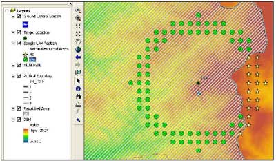
Figure 1. Candidate points passing visibility and restricted areas criteria are shown as stars.
Around the target area the UAV will fly at a pre-determined altitude. The altitude of each remaining candidates will be subtracted by ground elevation obtained from DEM to get the clearance. If a clearance is less than the specified value then that point is tagged as unsafe. Further, the look angles calculated from safe candidate points and the target will be checked with the camera specification. Points do not pass this criterion mean they are too far from the target and are removed from the list.
As the communication link between the UAV and the control unit via which command and data are transferred is terrestrial-based, all remaining candidate points are to be checked if they can be “seen” from the control station which is normally located at the airfield. Points fail this visibility test will be removed. The remaining points in the list are points where the UAVs can see the target, safe and able to communicate to the base. Figure 2 displays an example of such points
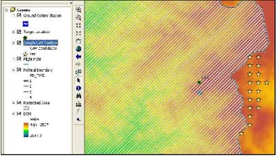
Figure 2. Points passing all criteria.
One of the remaining points will be selected by the mission planner and the flight path which is straight line connecting the selected point and the airfield is generated. Finally, aircraft capability specification e.g. speed, maximum altitude are used in the reverse calculation of way points coordinates and time from the target back to the airfield. Figure 3 shows the generated flight path.
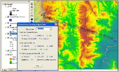
Figure 3. Flight path generated from the software module.
4. CONCLUDING REMARKS
Preliminary results suggested that the developed GIS-based mission planning module can improve the task of image intelligence. The pre-determined flight plan helps mission planners and flight commanders to visualize and perceive the whole mission in advance as well as enable them to control the aircraft more efficiently during the mission.
Flexibility of the module is the key improvement issue and two enhancements are being considered. The first one is to allow the users to have multiple target locations into any planning session while another one is to make the software capable to handle the locations of airfield and control station separately. Both enhancements are under development.
Another investigating issue is the impact of DEM accuracy on the result. The resolution of the DEM being used in the research is 100 m or DTED level 1 (NIMA, 1996) and is deemed by the involving research parties as too coarse especially in the rugged terrain in the north and western Thailand where targets are usually hidden in small valleys. DEM at resolution compatible to DTED level 2 (30m) and level 3 (10 m) will be generated using aerial photographs and high resolution satellite imageries. Result from the assessment will clarify the doubt regarding appropriate DEM resolution and serve as the guideline for further work.
REFERENCES
NIMA, 1996, Performance Specification Digital Terrain Elevation Data (DTED). Office of the Secretary Defense, 2002, Unmanned Aerial Vehicle Roadmap 2002 – 2027, Executive Summary, p.6.
ACKNOWLEDGEMENTS
The Research and Development for Unmanned Aerial Vehicle project is co-sponsored by the Thailand Research Fund (TRF) and the Ministry of Defense. The authors gratefully acknowledge their support of funding for this research. The authors also wish to express their appreciation to all officers from the artillery division for their valuable comments and feedbacks.