| GISdevelopment.net ---> AARS ---> ACRS 2002 ---> Photogrammetry |
The Positioning of SPOT
Stereo Images with a Local Orbit
Jung-Sheng Hsia and Ji-Rung Chen
Department of Surveying and Mapping Engineering,
Chung Cheng Institute of Technology,
Yuansulin, Tashi, Taoyuan, 335, Taiwan, R.O.C.
Tel: (886)-3-380-0364 Fax: (886)-3-380-0364 # 168
E-mail: mailto:jshsia%20@ccit.edu.tw
China Taipei
Jung-Sheng Hsia and Ji-Rung Chen
Department of Surveying and Mapping Engineering,
Chung Cheng Institute of Technology,
Yuansulin, Tashi, Taoyuan, 335, Taiwan, R.O.C.
Tel: (886)-3-380-0364 Fax: (886)-3-380-0364 # 168
E-mail: mailto:jshsia%20@ccit.edu.tw
China Taipei
Abstract:
The research aims at using the SPOT satellite ephemeris data with suitable weight when the bundle adjustment of SPOT stereo images is carried. With the aids of the weighted ephemeris data, the degree of the stability of the adjustment process can be increased. In addition, the number of ground control points needed for starting the adjustment can be reduced. In the mean time, a reasonable result can be given. The model uses SPOT satellite ephemeris data to determine the positions and attitudes of scan lines where the image points used in the bundle adjustment are located. The positions and the attitudes became as observations weighted in the model of bundle adjustment. As a result of that, a local orbit for SPOT stereo images is available to be determined. This may stabilize the adjustment process and decrease the number of ground control points needed.
The research shows the results of a sub-pixel level of positioning precision when using some ground control points as well as SPOT satellite orbital and ephemeris data with suitable weights. The model works well even when the number of ground control points is reduced to few. And its result is better than that of intersection method without using ground control points.
1. Introduction
The positioning method using stereo SPOT images have been developed in several models since the SPOT satellite was placed in the orbital in 1986. One way of positioning can be carried out with auxiliary satellite position and attitude data while using SPOT imagery without ground control points. The positioning accuracy however became very low. A general model of using collinearity condition equations can give results in a sub-pixel level of positioning accuracy. Exterior orientation parameters of a SPOT image are given as polynomial functions of time with second or third order. Therefore, an essential number of ground control points and iterations for estimating the coefficients of the polynomials increases. With the aids of constraints, satellite position and attitude rates, the essential number of ground control points can be decreased and the accuracy of SPOT image orientation can be improved (Shibasaki et al., 1988). A method has been developed with the aims of decreasing the number of ground control points and stabilizing the adjustment process with the assistant of local orbits estimated for each SPOT image by the use of auxiliary satellite position and attitude.
2. Method
The method is developed on the base of collinearity condition equations as shown in equation (1). The sensor positions and attitudes of SPOT imagery generally are approximated as polynomials shown in equation (2) and (3). The polynomials expressed as the functions of time in third and second order. This leads to 21 unknown coefficients. As a result of that, an essential number of ground control points increases and the convergence of the estimating process slow down. To tackle these issues, one of the methods is to use weighted observation equations of the ground control points and the attitudes of imagery. The equations can be expressed as the equations of (4) and (5). Finding suitable weight values for both equations becomes anothernewissue because of very high correlation among the coefficients. In order to reduce the impact of the issue, local orbit of each SPOT image can be estimated.
2.1 Local Orbit
SPOT satellite ephemeris data provides satellite attitude and position b ut their density and accuracy are not good enough to give better result and stability of estimated process. However, the satellite attitude and position of each line of image can be determined with the data provided in SPOT CCT. The determined satellite attitude and position are then expressed as equations (6) that are the function of time. Therefore, a local orbit for a SPOT image can be estimated by using satellite attitude and position of the line of image points that are selected and distributed evenly on the image. For each corresponding image point twelve observation equations are listed. It is not necessary to provide the ground coordinates of the corresponding image points when the local orbit is estimated. The coordinates of ground control points have to be provided while the estimate process is carried out. The local orbit has to satisfy with collinearity condition equation (1) and ground control point equation (4). The unknown parameters thus are estimated by means of solving equations (1), (4) and (6) with weighted nonlinear least squares method.
where M1=m11j(Mi - XLj)+m12j(Yi-YLj)+m13j(Zi-ZLj)
M2=m21j(Xi-XLj)+m22j(Yi-YLi)+m23j(Zi-ZLj)
M3M31j(X1-XLj)+m32j(Yi-YLj)+m33j(Zi-ZLj)
yi: Line Number of Image-3000 *13um,
Sy: Scale factor in y direction,
XLj , YLj , ZLj : Sensor position of the jth line,
Xi , Yi , Zi : Coordinates of the ith ground control point,
f : Focal length,
m11j ,…, m33j ˜Rotation matrix of attitude of the jth line.
where wjjj, kj , XLj , YLj , ZLj : The exterior orientation of the jth line, w0 , w1 , w2 , w3 , j0 , j1 , j2 , j3 , k0 , k1 , k2 , k3 , XL0 , XL1, XL2 , YL0 , YL1 , YL2 , ZL0 , ZL1 , ZL2 : The unknown coefficients of polynomials,
xi: Line number- 3000 x dt,
dt: The time interval between two lines, 1.504ms for SPOT imagery.
where Xi ,Yi ,Zi : The coordinates of ground control points,
Xi0,Yi0, Z0i : The initial coordinate values of the ground control points,
VXi , VYi , VZi : The residual values of coordinates of the ground control points,
dXi ,dYi ,dZi The correction values of coordinates of the ground control points,
where Vw0, VZL2: The residual of the coefficients of polynomials,
dw0, dZL2: The corrections of the coefficients of polynomials,
w0, ZL2 : The observation value of the coefficients of polynomials,
w00, ZL20: The initial values of the coefficients of polynomials.
where w1, j1, k1, XL1, YL1, ZL1 : The attitude and position of the ith line.
3. Test Area and Results
The test SPOT stereo images as shown in Figure 1 cover with the area of north part of Taiwan. Figure 1 also shows the distribution of the corresponding image points of both ground control points and check points. Their ground coordinates were measured on 1:5,000 scale photographic map. To know the efficient of the developed model, different methods have been applied with different number of ground control points.
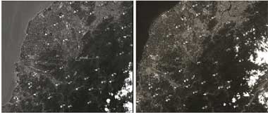
Figure 1 The test SPOT stereo images
Table 1 The RMS of check points while using intersection without ground control points
| R.M.S. (M) | ||
| X | Y | Z |
| 272.966 | 101.792 | 230.378 |
Table 1 shows that the accuracy of intersection with no ground control points in X,Y and Z directions is about two hundred meters. Using ageneral model of collinearity condition equatins can improve the positioning accuracy to a sub-pixel level when the number of ground control point is more than 22 as shown in Figure 2.
Figure 3 indicates that the accuracy of using local orbital model with high weight of satellite attitude is not good enough but can be improved by using high weight of satellite position as shown in Figure 4. Figure 4 also shows that the accuracy in Z direction is worse than in X and Y directions. However, better results shown in Figure 5 were given when the weights of satellite attitude and position were higher than that of ground control points. A sub-pixel level of accuracy can be given when the number of ground control points decreased to 14. When the number of ground control points is reduced to less than 6, results with lower accuracy can be obtained.
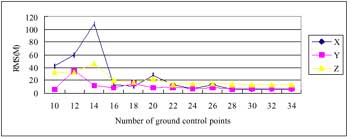
Figure 2 The RMS of check points while using general model of collinearity condition equations
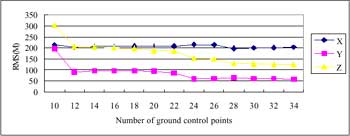
Figure 3 The RMS of check points while using local orbital model with high weight of satellite attitude
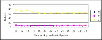
Figure 4 The RMS of check points while using local orbital model with high weight of satellite position
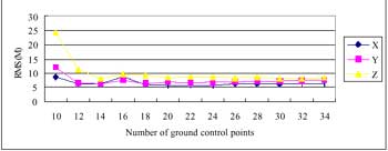
Figure 5 The RMS of check points while using local orbital model with reasonable weight
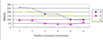
Figure 6 The RMS of check points while using local orbital model with few ground control points
4. Conclusions
This research has concentrated on the development of a model to position by means of SPOT stereo images with local orbits. The model has been tested in several cases with different weights and number of ground control points. Based on the test results, the following conclusions may be drawn:
With the aids of the local orbital model and suitable weight, an essential number of ground control points for the position of SPOT stereo imagery can be reduced. A Sub- pixel level of accuracy can be given when the number of ground control points is larger than 14. When the number of ground control points is less than 6, reasonable result still can be given.
Acknowledgment
The author would like to thank the National Science Council of the Republic of China for financially supporting this research under contract of No. NSC 91-2623-7-014-011
References
- Shibasaki, R., Murai, S., and Okuda, T., 1988. SPOT Imagery Orientation with Auxiliary Satellite Position and Attitude Data, I.S.P.R.S. Congress, COM III.