| GISdevelopment.net ---> AARS ---> ACRS 2000 ---> Poster Session 2 |
Optical Remote Sensing Using
Fiber Bragg Device For Dynamic Load Measurements
C.
Patimapornchai1, V. Jewpraditkul2 and
P.P.Yupapin3
1 Department of Control System and Instrumentation Engineering, Faculty of Engineering
2 Department of Physics, Faculty of Science
King Mongkut 's University of Technology Thonburi, Bangkok 10140, Thailand
3 Lightwave Technology Research Center (LTRC),
Department of Applied Physics Faculty of Science,
King Mongkut 's Institute of Technology Ladkrabang
Bangkok 10520, Thailand,
Tel: 7373000 ext. 6271/6213, Fax: 3269981
E-mail: Yupapin.Preecha@kmitl.ac.th
Abstract 1 Department of Control System and Instrumentation Engineering, Faculty of Engineering
2 Department of Physics, Faculty of Science
King Mongkut 's University of Technology Thonburi, Bangkok 10140, Thailand
3 Lightwave Technology Research Center (LTRC),
Department of Applied Physics Faculty of Science,
King Mongkut 's Institute of Technology Ladkrabang
Bangkok 10520, Thailand,
Tel: 7373000 ext. 6271/6213, Fax: 3269981
E-mail: Yupapin.Preecha@kmitl.ac.th
This work is the feasibility study of the dynamical load sensors, using optical remote measurement scheme. The optical sensing head is designed consisting of a fiber grating then spliced i.e. connected to a length of transmitted single mode fiber. The other end of the transmitted fiber is connected to the signals processing unit known as an optical time domain reflectometer (OTDR). The sensing head is sandwiched between a pair of sensing device buffer, where the applied loads can be applied on the sensing head. The measurement relationship between the reflected light intensity and applied loads are the subject of the investigation.
1. Introduction
Optical devices have been widely used either in sensors and communications [1-3]. An optical device known as fiber grating has also been investigated and used in both areas [4]. The use of such a device for temperature sensor has been reported [5], where grating was attached between two different materials where their thermal expansion effect the chane in grating period introducing the temperature measurement. The simultaneous measurement of temperature and strain was investigated [6], where two different physical parameters could be observed and measured using scch a siple and low cost technique. The use of fiber grating for the measurement of alternative current (ac) was reported by [7], the multimode laser diode was employed to relatively measure the change in modulated frequency respecting to the change in drived current. Fiber grating was also used in communication and signal processing system, to complement the idea of all fiber communication and networks [8].
The measurement relationship between the dynamical applied loads and output light intensity is detected by using OTDR, where the long length of single mode fiber is shown the remote sensing sense [9]. The measurement errors contributing by either small vibration or temperature changes are also our subject of this investigation. The remote sensing sense and the dynamical measurement are also the major objectives of this work. The application for fluid flow rate and transported load may be discussed.
2. Operating Principles
When coherent light from source enters into an optical system and sensing element as shown in Fig. 1, the coupled light from one end of the sensing fibers is reflected into the launching source, the other is reflected to the optical detector, Pr, which is expressed as [9]
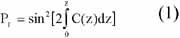
The coupling coefficient from equation (1) is given as
V(z) = a (z) k (n12-n22)1/2 (3)
d = 1-(n2/n1)2 (4)
and k = 2p/l. Where a is the coupling fiber radius, n1 and n2 are core and cladding refractive indices of the coupling fibers, respectively.l is light source wavelength.
The change in grating period,L, is formed the change in Bragg wavelength as
where lB is Bragg wavelength, m = 1, 2, 3…..is the reflection grating wavelength order. nc is fiber optic refractive index and G is Bragg grating period.
When force is applied on he sensing unit that the change in grating period occurs inducing the change in output reflected light, Pr, which is observed by detector.
3. Experiment
The experimental system set up may be used an optical sytem or OTDR. A coherent light from a laser diode with wavelength of 1.31 micron is employed then launched into a length of a single mode fiber as shown in Figure 1, in the measurement system by the OTDR, before entering into a sensing unit i.e. fiber Bragg device or fiber grating. The return signals either from the applied loads or fiber end itself is detected then seen on the OTDR monitor. The change in output signal intensity relating to the applied loads is observed respecting to the sensing head position, with dynamical and real times processing. The bulky signal detection using grating and the scanning detector are also our subject to be investigated.
The measurement relationship between the dynamical applied loads and output light intensity is detected by using OTDR. The reflected light output from sensing unit is splitted and observed by using bulky grating before entering into detector. The change in output light intensity may be relatived to he change in applied loads.
4. Discussion And Conclusion
The research work is being continued in progress that the expected experimental scheme and results should be realized by the conference time.
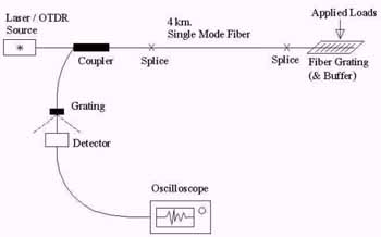
Figure 1 Illustrates of the experimental system use for dynamic load measurement.
The dynamic measurement means the measurement is taken place when load is in under movement condition. For examples, the measure of fluid in plastic pipe, the measurement of transported vehicles in the traffic.
5. Acknowledgement
The authors are pleased to acknowledge support from National Science and Technology Development Agency of Thailand (NSTDA) by way of a research scholarship to Ms. C. Patimapornchai.
References
- Udd, E., 1991. Fiber optics sensors : An introduction for engineers and scientists, John Wiley & Sons, Toronto, pp. 443-445.
- Wright, J.V.,1986. Wavelength dependence of fused couplers. Electron. Lett., 22, pp. 320-321.
- Gonthier, F. et al, 1987. Investigation of power oscillations along tapered monomode fibers measurements and analyses of fields in fused tapered single mode fiber couplers. Appl. Opt., 26, pp. 444-449.
- Hill, K.O. and Meltz, G., 1997. Fiber Bragg Grating Technology Fundamentals and Overview. Journal of Lightwave Technology, 15(8), pp. 1263 - 1276.
- Jung, J. et al, 1999. Fiber Bragg grating temperature sensor with controllable sensitivity. Appl. Opt., 38(13), pp. 2752 - 2754.
- Jung, J. et al, 2000. Simultaneous measurement of strain and temperature by use of a single fiber Bragg grating written in an erbium: yttbium - doped fiber. Appl. Opt., 39(7), pp. 1118 - 1120.
- Ferreira, L.A. et al, 1999. Demodulation of fiber Bragg grating sensors based on dynamic tuning of a multimode laser diode. Appl. Opt., 38(22), pp. 4751 - 4759.
- Mayer, E. and Basting, D., 2000. Excimer - laser advance aid production of fiber grating. Laser Focus World, April, pp. 107 - 110.
- Raknoi, P. and Yupapin, P.P., 2000. Optical remote measurement technique using loop-mirrors sensing fibers, Science Asia, (in press).