| GISdevelopment.net ---> AARS ---> ACRS 2000 ---> Image Processing |
Geometric Registration Method
For 10-Day Composite Avhrr Data For Asian Region
Ts. Purevdorj and R.Yokoyama
Department of Computer Science, Faculty of Engineering, Iwate University, Japan
E-mail :mailto:dorj@cis.iwate-u.ac.jp, yokoyama@cis.iwate-u.ac.jp
Ts. Purevdorj and R.Yokoyama
Department of Computer Science, Faculty of Engineering, Iwate University, Japan
E-mail :mailto:dorj@cis.iwate-u.ac.jp, yokoyama@cis.iwate-u.ac.jp
Keywords: AVHRR, geometric correction,
registration, GCP, matching, edge line
Abstract
This paper describes a geometric registration method for compositing AVHRR images. In the method, we consider two problems to improve geometric registration accuracy. The first is a development of automated detection procedure for GCPs locations in AVHRR imagery. The second is to develop image to map registration procedure for fine correction. Using the existing and developed methods, the geometric registration is carried out in two stages. In the first stage-correction, an accuracy of AVHRR image navigation is increased by automated technique of GCPs identification and correction of terrain elevation. In the second, the navigated AVHRR image is overlaid on reference coastline image for determination offsets and a final correction is carried out by registration of the navigated image to fixed reference image. This method was implemented by using "C" under UNIX operating system in HP workstation and has been operationally used for geometric registration of AVHRR composite data without operator intervention. The registration software package is applicable to any pre-processed AVHRR data for fine geometric correction.
1. Introduction
The availability of daily Advanced Very High Resolution Radiometer (AVHRR) imagery which covers very large regions has been shown to be useful for monitoring global and continental environmental conditions. AVHRR imagery has major advantages such as high frequent overpass and wide scanning provide the chance of producing cloud free images by compositing AVHRR images collected in regular intervals (3). However, for users of the data, it has been often showed difficult to pre-process and produce multi-temporal AVHRR composite data set. One of the most difficult problems in the compositing process is to provide high accuracy of geometric correction for each individual scene to be composited.
This paper considers improvements on geometric correction in two ways and designing full registration system for AVHRR composite data. The first improvement is the increase of systematic correction accuracy using automated detection procedure of GCPs locations in AVHRR imagery and elevation data. The second is to develop an automated image registration of navigated AVHRR images to fixed map image.
2. Method
The approach of accurate geometric registration used in the compositing AVHRR data consists of two-stage correction procedures. In the first stage of correction is to calculate ground location of the image pixels using an orbital model and it includes two steps: identification of GCPs and AVHRR image navigation. The second stage correction is motivated by the need to increase multitemporal positional accuracy of the navigated images for compositing requirement and it includes estimation of navigation accuracy, determination of mapping function and resampling. A flow of geometric registration method for composite AVHRR data set is shown in Figure 1. In the registration approach, we use PaNDA package for image navigation procedure and the rest of all steps were developed.
Figure 1. Processing steps for geometric registration of AVHRR data
3. Development Of Geographical Database
The registration procedure developed requires the use of geographical database consisting of GCPs data set, ground control matching pattern (GCMP), reference overlay image of geographic features such as coastline and rivers and elevation data. Therefore, these geographical databases were created in the software development stage.
The geographical database used in the geometric registration includes coastline vector data, elevation data, and library of GCPs and GCMPs. These data are used to precise identification of GCPs positions in satellite and ground projections, and accurate matching of shape similarity. The coastline vector data were created from Digital Chart of the World (DCW). However, the vector data created from only DCW does not fully satisfy our requirement, because data for rivers are not available in DCW. When image to map registration is used, the digital data for rivers are extremely important where lakes or coastal data are not available. Therefore, the hydrological feature of rivers was generated from water mask data (EROS DATA Center) and added to the vector data. Each of the points included in the vector data, has latitude, longitude and elevation values.
The coastline vector data was converted to reference overlay image of coastline. GCPs data set was created from the reference overlay image by selecting easily detectable and most suitable locations for matching procedure. Using the reference overlay image, land and water mask image had been created and then it was used to generate bitmap image chips with 32 by 32 pixels size for pattern matching of shape similarity. Each of these chips is assigned GCP location, which we are referred to as GCMP.
The digital elevation data used for correction for terrain elevation were generated from GTOPO30 according to whole coverage area of the final composite data set.
4. First-Stage Correction
4.1. Identification of GCPs locations in AVHRR imagery
The shifts of GCPs locations in AVHRR image from the corresponding locations in the reference overlay image is determined by matching image window of edge line derived from AVHRR image with binary template image extracted from the reference overlay image. We refer these images as to searching window and reference window respectively and they are created using same ground point selected from the GCP data set.
The reference window of edge line is created in the following way. Before the matching procedure, once the reference overlay image had been created in satellite projection from the coastline vector data described in section 3. The reference overlay image includes coast and shorelines of the area, which is exactly same as whole coverage area of the raw AVHRR imagery. Then the reference window of 32 by 32 binary data is extracted from the reference overlay image centered GCP position.
The searching window from raw AVHRR imagery is created in the following way. At first, an image window of 64 by 64 data is extracted from raw AVHRR channel 1, 2 and corresponding pixel numbers centered at selected GCP position (Figure 2, 2nd and 3rd columns). The channel 1 and 2 were calibrated and a suitability of the image window for the subsequent matching process is tested by cloudiness and sensor scan angle.
A searching window of edge line for the matching is created from the image window by edge extraction using NDVI value, an adaptive thresholding and filtering. Thus three searching windows of edge line for each GCP were produced: first one by NDVI value (Figure 2, 4-th column) and second one by spatial filtering method (Figure 2, 5-th column) and third one by optimal thresholding method (Figure 2, 6-th column). In the searching window, cloudy pixels belonging to edge line are not used for matching.
After the reference window and searching windows had been generated, a similarity between the two windows is determined by image correlation procedure. In the result of image correlation procedure, the location of selected GCP was determined simultaneously in the three searching windows and the searching window with maximum correlation coefficient was selected (Figure 2, the area where best match occurs is marked by small window in the searching windows).
4.2 AVHRR image navigation
A final step of first stage correction is the conversion of each line and sample numbers of raw AVHRR imagery to corresponding earth locations. In this step, a set of GCPs determined by automated image matching, were used for adjustment of orbital parameters and satellite attitude correction. Then the conversion procedure is realized by indirect navigation method using PaNDA package (1,2). However, PaNDA package does not consider elevation effect in image navigation procedure because elevation data were not adapted to the package. The analysis showed that if an elevation is not considered for in the image navigation procedure, registration errors for off-nadir pixels can occur up to 4 pixels in high land areas. Therefore, elevation data created from GTOPO 30 were added to the PaNDA and earth location of each pixel of AVHRR imagery was calculated considering elevation effect in image navigation. Thus, first stage correction results in determining line and sample numbers of satellite image for given latitude and longitude of Plate Carree projection coordinate system. The navigation procedure is also used to compute sun-target geometry angles for each pixel.
5. Second-Stage Correction
Error evaluation of calculated ground locations of raw imagery showed that AVHRR image navigation does not work well over the whole image. Moreover, test composite data produced from the images corrected by only first-stage correction procedure showed that navigation accuracy does not satisfy compositing requirement and it was easily observed that small lakes and rivers were significant blurred in the composite image. Therefore, in order to achieve satisfactory accuracy for multitemporal compositing, it was necessary to register the each navigated image to fixed map overlay image. This reason motivates to develop second stage correction that is carried out in three steps: estimation of navigation accuracy, determination of mapping function and resampling.
5.1 Determination of navigation accuracy
A positional accuracy of the navigated image is determined by the correspondence between the reference overlay image and the navigated image. The correspondence is established by precise matching GCMPs as reference windows with searching windows in Plate Carree projection. The reference window in this step is the land and water surface pattern surrounding the center point of GCP. The GCMPs (Figure 2, A1~F1) described in section 3 are used as reference window in the pattern matching procedure. Simultaneously, an image window of 64 by 64 size centered at the same location as for the GCMP, is produced from raw imagery referring calculated ground location points. Then the image window is used to generate searching window of binary data of "1" for land or "0" for water (Figure 2, A3~F5). Then, the image correlation method described in section 4.1, is applied to match the reference and searching windows. The result of the matching procedure is a set of GCPs locations both in the navigated and reference overlay images. Thus, the set of GCPs selected allows estimating navigation errors and they are used for determination mapping function for final correction.
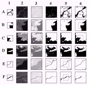
Figure 2. GCMP's and searching windows used in matching. 1-GCMP's, 2, 3- Ch2 and NDVI image windows extracted from raw AVHRR data, 4,5,6- searching windows extracted by NDVI, filtering and adaptive threshold value respectively.
The resampling process includes two steps. The first is determination of polynomial mapping function. Applying least square method to the set of GCPs selected in previous step, the polynomial mapping functions of degree two is established and they are formulated as following:
xi = a0 + a1*Xi + a2*Yi + a3*Xi*Yi + a4* Xi2 + a5*Yi2
yi = b0 + b1*Xi+ b2*Yi + b3*Xi*Yi+ b4* Xi2 + b5*Yi2
where xi and yi correspond to a point in the navigated image, Xi and Yi correspond to a point in the corrected image. Using the set of GCMPs, the unknown coefficients a0~a5 and b0~b5 were determined by minimizing the sum of squared errors using least-squares technique.
Using the mapping functions, the resampling procedure is carried out in the final step. The resampling is performed by transformation of pixel locations in the navigated image to corresponding locations in the resulting output image. In the transformation, nearest neighbour interpolation technique is used.
6. Evaluation Of Errors In Registration Accuracy
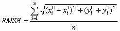
It is reasonable to measure geometric correction quality for all over image by RMSE obtained from the GCPs different from those used to determine the mapping functions. Therefore we used the estimation approach in which the accuracy of the geometric registration method was evaluated by calculation RMSE and mean deviations of the GCMPs for samples and lines when a geometrically corrected image was overlaid on the reference overlay image. The reference overlay image was generated from the geographical database. For test, we used AVHRR HPRT data acquired from August 1 to August 10 of 1999 at Ulaanbaatar (Mongolia). In the first experiment, RMSE and mean deviations of pixels and lines were estimated from the image that is not corrected by terrain elevation and GCPs. The result is compared with the accuracy of the image corrected by terrain elevation and GCPs (Table 1). The RMSE is represented by
In the second test, two-stage correction was carried out for the each single scene and daily mosaic images were produced. Then RMSE and mean deviations were estimated from the daily mosaic images (Table 1). Table 1 clearly showed that GCPs matching result and terrain correction give significant improvement in the first stage of geometric correction. However, it can be seen that accuracy of the first stage correction is not sufficient for compositing requirement. Comparison of two-stage correction result shows that fine correction allows getting images with much better accuracy than the images performed by only first-stage correction.
Table 1. RMSE comparison of the correction steps for daily composite images
Table 2. RMSE comparison of the correction steps for 10 day composite image
Conclusions
A full automatic method of geometric registration used of AVHRR data has been presented. This approach based on two-stage correction algorithm has been used in the geometric registration of composite AVHRR data set for Asian region with satisfactory result. The increase of registration accuracy of AVHRR imagery has been achieved by two improvements. In the first, an accuracy of AVHRR image navigation using PaNDA package is improved by accurate identification of GCPs and terrain correction. In the second, AVHRR image navigation accuracy is estimated and a final correction is carried out by registration of the navigated images to fixed reference image. Realizing this algorithm, we developed the registration software in "C" and implemented it under UNIX operating system in HP workstation. This software has been operationally used for geometric registration of AVHRR data and it is applicable to pre-processed AVHRR data for fine geometric correction without any operator intervention.
The development of the composite data set has been shown that registration of AVHRR data for large area with subpixel accuracy is somewhat difficult in practical realization. The difficulties have arisen due to several problems discussed in previous sections: inaccuracies in navigation model and coast and shoreline data, also some errors in orbital parameters. Specially, these problems are very important to resulting accuracy when operational registration system has been used and they are long-term issues for the increase registration accuracy.
In spite of the existing difficulties, we consider some way to improve present accuracy in the future. The overlay of the coastline image on AVHRR imagery showed that there are non-uniform shifts across the whole navigated image. In this case the use of ordinary polynomial mapping function for image transformation determined by least-squares technique may not enough to get more higher accuracy because a local geometric distortions are equally averaged for all over the image. Therefore, utilization of mapping functions, which is sensitive to local distortions, is one of the possible ways to improve the overall registration accuracy.
References
Abstract
This paper describes a geometric registration method for compositing AVHRR images. In the method, we consider two problems to improve geometric registration accuracy. The first is a development of automated detection procedure for GCPs locations in AVHRR imagery. The second is to develop image to map registration procedure for fine correction. Using the existing and developed methods, the geometric registration is carried out in two stages. In the first stage-correction, an accuracy of AVHRR image navigation is increased by automated technique of GCPs identification and correction of terrain elevation. In the second, the navigated AVHRR image is overlaid on reference coastline image for determination offsets and a final correction is carried out by registration of the navigated image to fixed reference image. This method was implemented by using "C" under UNIX operating system in HP workstation and has been operationally used for geometric registration of AVHRR composite data without operator intervention. The registration software package is applicable to any pre-processed AVHRR data for fine geometric correction.
1. Introduction
The availability of daily Advanced Very High Resolution Radiometer (AVHRR) imagery which covers very large regions has been shown to be useful for monitoring global and continental environmental conditions. AVHRR imagery has major advantages such as high frequent overpass and wide scanning provide the chance of producing cloud free images by compositing AVHRR images collected in regular intervals (3). However, for users of the data, it has been often showed difficult to pre-process and produce multi-temporal AVHRR composite data set. One of the most difficult problems in the compositing process is to provide high accuracy of geometric correction for each individual scene to be composited.
This paper considers improvements on geometric correction in two ways and designing full registration system for AVHRR composite data. The first improvement is the increase of systematic correction accuracy using automated detection procedure of GCPs locations in AVHRR imagery and elevation data. The second is to develop an automated image registration of navigated AVHRR images to fixed map image.
2. Method
The approach of accurate geometric registration used in the compositing AVHRR data consists of two-stage correction procedures. In the first stage of correction is to calculate ground location of the image pixels using an orbital model and it includes two steps: identification of GCPs and AVHRR image navigation. The second stage correction is motivated by the need to increase multitemporal positional accuracy of the navigated images for compositing requirement and it includes estimation of navigation accuracy, determination of mapping function and resampling. A flow of geometric registration method for composite AVHRR data set is shown in Figure 1. In the registration approach, we use PaNDA package for image navigation procedure and the rest of all steps were developed.
Figure 1. Processing steps for geometric registration of AVHRR data
3. Development Of Geographical Database
The registration procedure developed requires the use of geographical database consisting of GCPs data set, ground control matching pattern (GCMP), reference overlay image of geographic features such as coastline and rivers and elevation data. Therefore, these geographical databases were created in the software development stage.
The geographical database used in the geometric registration includes coastline vector data, elevation data, and library of GCPs and GCMPs. These data are used to precise identification of GCPs positions in satellite and ground projections, and accurate matching of shape similarity. The coastline vector data were created from Digital Chart of the World (DCW). However, the vector data created from only DCW does not fully satisfy our requirement, because data for rivers are not available in DCW. When image to map registration is used, the digital data for rivers are extremely important where lakes or coastal data are not available. Therefore, the hydrological feature of rivers was generated from water mask data (EROS DATA Center) and added to the vector data. Each of the points included in the vector data, has latitude, longitude and elevation values.
The coastline vector data was converted to reference overlay image of coastline. GCPs data set was created from the reference overlay image by selecting easily detectable and most suitable locations for matching procedure. Using the reference overlay image, land and water mask image had been created and then it was used to generate bitmap image chips with 32 by 32 pixels size for pattern matching of shape similarity. Each of these chips is assigned GCP location, which we are referred to as GCMP.
The digital elevation data used for correction for terrain elevation were generated from GTOPO30 according to whole coverage area of the final composite data set.
4. First-Stage Correction
4.1. Identification of GCPs locations in AVHRR imagery
The shifts of GCPs locations in AVHRR image from the corresponding locations in the reference overlay image is determined by matching image window of edge line derived from AVHRR image with binary template image extracted from the reference overlay image. We refer these images as to searching window and reference window respectively and they are created using same ground point selected from the GCP data set.
The reference window of edge line is created in the following way. Before the matching procedure, once the reference overlay image had been created in satellite projection from the coastline vector data described in section 3. The reference overlay image includes coast and shorelines of the area, which is exactly same as whole coverage area of the raw AVHRR imagery. Then the reference window of 32 by 32 binary data is extracted from the reference overlay image centered GCP position.
The searching window from raw AVHRR imagery is created in the following way. At first, an image window of 64 by 64 data is extracted from raw AVHRR channel 1, 2 and corresponding pixel numbers centered at selected GCP position (Figure 2, 2nd and 3rd columns). The channel 1 and 2 were calibrated and a suitability of the image window for the subsequent matching process is tested by cloudiness and sensor scan angle.
A searching window of edge line for the matching is created from the image window by edge extraction using NDVI value, an adaptive thresholding and filtering. Thus three searching windows of edge line for each GCP were produced: first one by NDVI value (Figure 2, 4-th column) and second one by spatial filtering method (Figure 2, 5-th column) and third one by optimal thresholding method (Figure 2, 6-th column). In the searching window, cloudy pixels belonging to edge line are not used for matching.
After the reference window and searching windows had been generated, a similarity between the two windows is determined by image correlation procedure. In the result of image correlation procedure, the location of selected GCP was determined simultaneously in the three searching windows and the searching window with maximum correlation coefficient was selected (Figure 2, the area where best match occurs is marked by small window in the searching windows).
4.2 AVHRR image navigation
A final step of first stage correction is the conversion of each line and sample numbers of raw AVHRR imagery to corresponding earth locations. In this step, a set of GCPs determined by automated image matching, were used for adjustment of orbital parameters and satellite attitude correction. Then the conversion procedure is realized by indirect navigation method using PaNDA package (1,2). However, PaNDA package does not consider elevation effect in image navigation procedure because elevation data were not adapted to the package. The analysis showed that if an elevation is not considered for in the image navigation procedure, registration errors for off-nadir pixels can occur up to 4 pixels in high land areas. Therefore, elevation data created from GTOPO 30 were added to the PaNDA and earth location of each pixel of AVHRR imagery was calculated considering elevation effect in image navigation. Thus, first stage correction results in determining line and sample numbers of satellite image for given latitude and longitude of Plate Carree projection coordinate system. The navigation procedure is also used to compute sun-target geometry angles for each pixel.
5. Second-Stage Correction
Error evaluation of calculated ground locations of raw imagery showed that AVHRR image navigation does not work well over the whole image. Moreover, test composite data produced from the images corrected by only first-stage correction procedure showed that navigation accuracy does not satisfy compositing requirement and it was easily observed that small lakes and rivers were significant blurred in the composite image. Therefore, in order to achieve satisfactory accuracy for multitemporal compositing, it was necessary to register the each navigated image to fixed map overlay image. This reason motivates to develop second stage correction that is carried out in three steps: estimation of navigation accuracy, determination of mapping function and resampling.
5.1 Determination of navigation accuracy
A positional accuracy of the navigated image is determined by the correspondence between the reference overlay image and the navigated image. The correspondence is established by precise matching GCMPs as reference windows with searching windows in Plate Carree projection. The reference window in this step is the land and water surface pattern surrounding the center point of GCP. The GCMPs (Figure 2, A1~F1) described in section 3 are used as reference window in the pattern matching procedure. Simultaneously, an image window of 64 by 64 size centered at the same location as for the GCMP, is produced from raw imagery referring calculated ground location points. Then the image window is used to generate searching window of binary data of "1" for land or "0" for water (Figure 2, A3~F5). Then, the image correlation method described in section 4.1, is applied to match the reference and searching windows. The result of the matching procedure is a set of GCPs locations both in the navigated and reference overlay images. Thus, the set of GCPs selected allows estimating navigation errors and they are used for determination mapping function for final correction.
Figure 2. GCMP's and searching windows used in matching. 1-GCMP's, 2, 3- Ch2 and NDVI image windows extracted from raw AVHRR data, 4,5,6- searching windows extracted by NDVI, filtering and adaptive threshold value respectively.
The resampling process includes two steps. The first is determination of polynomial mapping function. Applying least square method to the set of GCPs selected in previous step, the polynomial mapping functions of degree two is established and they are formulated as following:
xi = a0 + a1*Xi + a2*Yi + a3*Xi*Yi + a4* Xi2 + a5*Yi2
yi = b0 + b1*Xi+ b2*Yi + b3*Xi*Yi+ b4* Xi2 + b5*Yi2
where xi and yi correspond to a point in the navigated image, Xi and Yi correspond to a point in the corrected image. Using the set of GCMPs, the unknown coefficients a0~a5 and b0~b5 were determined by minimizing the sum of squared errors using least-squares technique.
Using the mapping functions, the resampling procedure is carried out in the final step. The resampling is performed by transformation of pixel locations in the navigated image to corresponding locations in the resulting output image. In the transformation, nearest neighbour interpolation technique is used.
6. Evaluation Of Errors In Registration Accuracy
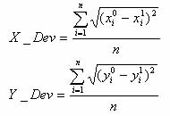
It is reasonable to measure geometric correction quality for all over image by RMSE obtained from the GCPs different from those used to determine the mapping functions. Therefore we used the estimation approach in which the accuracy of the geometric registration method was evaluated by calculation RMSE and mean deviations of the GCMPs for samples and lines when a geometrically corrected image was overlaid on the reference overlay image. The reference overlay image was generated from the geographical database. For test, we used AVHRR HPRT data acquired from August 1 to August 10 of 1999 at Ulaanbaatar (Mongolia). In the first experiment, RMSE and mean deviations of pixels and lines were estimated from the image that is not corrected by terrain elevation and GCPs. The result is compared with the accuracy of the image corrected by terrain elevation and GCPs (Table 1). The RMSE is represented by
In the second test, two-stage correction was carried out for the each single scene and daily mosaic images were produced. Then RMSE and mean deviations were estimated from the daily mosaic images (Table 1). Table 1 clearly showed that GCPs matching result and terrain correction give significant improvement in the first stage of geometric correction. However, it can be seen that accuracy of the first stage correction is not sufficient for compositing requirement. Comparison of two-stage correction result shows that fine correction allows getting images with much better accuracy than the images performed by only first-stage correction.
Table 1. RMSE comparison of the correction steps for daily composite images
| Day | Syst. Corr. | Stage-one | Stage-two |
| 1 | 17.534 | 3.918 | 1.679 |
| 2 | 16.283 | 4.254 | 1.873 |
| 3 | 15.412 | 5.236 | 2.134 |
| 4 | 15.207 | 4.692 | 1.580 |
| 5 | 14.735 | 5.399 | 2.463 |
| 6 | 15.783 | 3.899 | 2.238 |
| 7 | 17.496 | 4.697 | 1.628 |
| 8 | 16.786 | 5.184 | 1.826 |
| 9 | 14.428 | 5.428 | 2.176 |
| 10 | 14.746 | 5.876 | 1.876 |
Table 2. RMSE comparison of the correction steps for 10 day composite image
| Syst. Corr. | Stage-one | Stage-two | |
| GCP | 25 | 168 | 168 |
| X_DEV | 7.28 | 3.301 | 1.598 |
| Y_DEV | 12.16 | 2.863 | 0.963 |
| RMSE | 14.063 | 4.701 | 1.969 |
Conclusions
A full automatic method of geometric registration used of AVHRR data has been presented. This approach based on two-stage correction algorithm has been used in the geometric registration of composite AVHRR data set for Asian region with satisfactory result. The increase of registration accuracy of AVHRR imagery has been achieved by two improvements. In the first, an accuracy of AVHRR image navigation using PaNDA package is improved by accurate identification of GCPs and terrain correction. In the second, AVHRR image navigation accuracy is estimated and a final correction is carried out by registration of the navigated images to fixed reference image. Realizing this algorithm, we developed the registration software in "C" and implemented it under UNIX operating system in HP workstation. This software has been operationally used for geometric registration of AVHRR data and it is applicable to pre-processed AVHRR data for fine geometric correction without any operator intervention.
The development of the composite data set has been shown that registration of AVHRR data for large area with subpixel accuracy is somewhat difficult in practical realization. The difficulties have arisen due to several problems discussed in previous sections: inaccuracies in navigation model and coast and shoreline data, also some errors in orbital parameters. Specially, these problems are very important to resulting accuracy when operational registration system has been used and they are long-term issues for the increase registration accuracy.
In spite of the existing difficulties, we consider some way to improve present accuracy in the future. The overlay of the coastline image on AVHRR imagery showed that there are non-uniform shifts across the whole navigated image. In this case the use of ordinary polynomial mapping function for image transformation determined by least-squares technique may not enough to get more higher accuracy because a local geometric distortions are equally averaged for all over the image. Therefore, utilization of mapping functions, which is sensitive to local distortions, is one of the possible ways to improve the overall registration accuracy.
References
- Hashimoto, T. and Murai, C., 1993, geometric correction of NOAA AVHRR Imagery in accordance with the number of GCPs, Journal of the Japan Society of Photogrammetry and Remote Sensing, 13.
- PaNDA User Manual, 1998.
- Yokoyama, R., Lei, L., Purevdorj, Ts. and Tanba, S., 2000, AVHRR 10-day Mosaic Composite Image Data Set for Asian Region, Journal of the Japan Society of Photogrammetry and Remote Sensing, Vol. 39, No.1, 33-38