| GISdevelopment.net ---> AARS ---> ACRS 2000 ---> Mapping from Space & GPS |
A Method Of Map Matching For
Personal Positioning Systems
Kay KITAZAWA, Yusuke
KONISHI, Ryosuke SHIBASAKI
Ms., Center for Spatial Information Science,
The University of Tokyo Center for Spatial Information Science,
Institute of Industrial Science The University of Tokyo
4-6-1 Komaba, Meguro-ku,Tokyo 153-8505
JAPAN
Tel. +81-3-5452-6417 Fax. +81-3-5452-6417
E-mail: kitazawa@iis.u-tokyo.ac.jp
Keywords:
Map matching, Positioning, Human, 3D-space,
gyroMs., Center for Spatial Information Science,
The University of Tokyo Center for Spatial Information Science,
Institute of Industrial Science The University of Tokyo
4-6-1 Komaba, Meguro-ku,Tokyo 153-8505
JAPAN
Tel. +81-3-5452-6417 Fax. +81-3-5452-6417
E-mail: kitazawa@iis.u-tokyo.ac.jp
Abstract
To track human's movements with high accuracy in certain areas, where GPS system is not available, complimentary positioning methods are needed. Personal positioning system using a sensor of acceleration and a gyrocompass together with GPS is now being developed as one of promising methods. Accumulation of positioning errors, however, cannot be avoided. One of the solutions to reduce or modify these errors is "Map matching" technique, which modifies estimated user's position assuming that users are always along road networks.
In this paper, a method of Map Matching for Personal Positioning Systems is proposed. While it has already been in practical use for car navigation systems, its simple algorithm based on distance and direction estimation is not sufficient for tracking of man's complicated movement. In addition, matching should be done for three-dimension maps because human movement consists of both vertical and horizontal motion. The algorithm proposed in this paper combines two of the current algorithms, one of which is based on matching one's shift patterns with shapes of road network, and the other is for a frequent step-by-step adjustment of one's estimated position against outlines of objects around it. Using this integrating algorithm, we propose a new Map Matching method that would give good performance in terms of accuracy of positioning system for human movement in 3D space.
Background
A demand for the accurate positioning technology is increasing. Though several positioning services are already in practical use, there are still some areas left to which radio waves used in such positioning systems cannot reach. Complimentary positioning methods for covering these areas are strongly needed. Though Personal Positioning System using a sensor of acceleration and a gyrocompass together with GPS to trace a person by his/her footsteps and angles is now being developed as one of promising methods, such system calculating one's relative position always accompanies an accumulation of positioning errors. To reduce or prevent these errors to make such system as much accurate as GPS, "Map Matching" technique, which modifies user's estimated position based on the assumption that users are always along road networks on the map is combined with it.
The quite simple algorithm used in current car navigation system is not enough for Personal Positioning System. Data from sensor of acceleration and a gyrocompass such as the number of footsteps and direction is not as accurate as that from sensor of rotation and angle of wheel. In addition, while the assumption used in this algorithm that car runs always on and along roadways allows the system to reconcile the car's estimated position and correspondent point on the center line of road network described by nodes and edges in the database, complicated and various patterns of human's movement cannot be limited to the center line network of roads. For example, it is necessary for a human tracking system to determine on which side of the street or in which floor the user is now walking. (Figure 1.) As a solution of this problem, using three-dimensional database in which roads are represented by polygonal planes, a new map matching method which can cope with unsteadiness of human's movement both for vertical and horizontal direction is proposed in this paper.
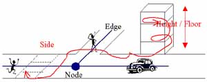
Fig. 1 Human can move more freely than cars on road networks
Review:Current Map Mathicng Algorithms
As a beginning, we overview current Map Matching methods and point out their problems to highlight the differences between our approach. Current methods can be classified into two types in large. The first one makes use of distinctive features of both human's shift pattern and road networks to find a corresponding point. In other words, similarity or correlation between the trajectory up to that time (position) and alignment of the road network around is calculated to choose an edge on which user most likely exists when conspicuous change in movements such as turning at corner occurs. The clue for matching is "turn at the corner". Since this is a non-regular event, it often happens that user keeps on going straight without any turn or other distinctive movement and the time interval of matching process is prolonged consequently, which brings accumulation of errors. The other method, on the other hand, just calculates distances between the estimated position and neighboring edges in very short term. Miyata(1991) suggests a methods with frequent calculation that enables relocation of estimated position before it goes too far away from the road networks to find correct point. Though this methods works well to avoid mismatching based on accumulation of errors, the brief algorithm designed for frequent position correction fails to modify the location if once mismatching occurs by selecting wrong edges. It has been shown in recent investigation that the mismatching occurs mainly near crossroads, that is, pros and cons of the second method are complementary to those of the first one. Then the approach we are going to take here uses both algorithms together in the process of map matching.
Main Points of Algorithm
Before we describe the algorithm in detail, we would like to make some remarks on principle and basic structure of it.
Principle
We refer to either of two databases, one of which consists of point's data for boundaries of objects and polygons and the other is a network made by nodes and edges. Coordinates and time of each estimated point and each corresponding modified point are separately stored in these databases.
The estimated position at each step is put on the map as it is unless it crosses outlines of objects such as the line of a wall surface. This means we relocate the points not on a network, but on an area of the object. When an intersection is found, the current and previous position is locally modified so that the modified point comes within the correct object. This is based on the frequent modification method. Modified points are used for showing user's position immediately.
Keeping on using this algorithm, if the change of direction (angle) gets bigger than threshold, all of the points included in the trajectory from previous change to that point are globally modified. This algorithm succeeds a judgment of similarity in forms and corrects whole trajectory itself so that the point at which angle changes can fit the corner. The database of network is used in this algorithm.
Local Modification
The estimated position is locally relocated according to the angles made by tracks and an outline when they have an intersection. If the angle is smaller than threshold, we assume that this incorrect positioning is brought by drift errors of gyrocompass and rotate the current point around the former one in proportion to that angle. If the angle is bigger than threshold, the track may hit against outlines because of its error in length (distance). Relocation of the current position is done by adjustment of the length of tracks.
Global Modification
We switch the algorithm for relocation to the global modification when sudden and sharp change of direction occurs between several steps with almost the same direction data. Searching the database of road networks for a crossroads or a curve with similar change in angle around the intersection, the edge on which user most likely locates is chosen. Compared with the shape of corresponding corner, an angle and length of tracks is modified.
Algorithm
The algorithm is shown in flowcharts (Figure 2 , 3)
The main process of Map Matching is as follows.
- Coordinates and time of the currently estimated and the previous position are obtained from the storage of positional data.(x, y, z, T)
- Tracks expressed by a vector between these two points is calculated
- Errors are modified by coefficients for correction of distance and angle.
- The values of these coefficients are obtained in of the previous Map Matching process.
- Data of the objects near the estimated position is obtained
- Whether the tracks cross the outlines of objects around them is checked. If there is one, we move into process 1. If not, coordinates and time of the estimated position are adopted as those of modified.
- Data of modified current position is obtained and added to the
storage of positional data.
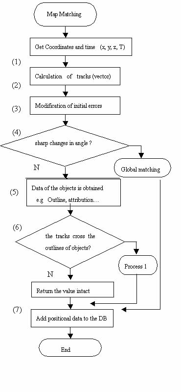
Figure 2 Flow chart of Map Matching (Main)
Next, process 1 is as follows.
- Whether intersection point of tracks and outlines is within the object "entrance" is checked. If so, coordinates and time of the estimated position are adopted as those of modified. If not, the whole tracks from the nearest corner are obtained.
- The most recent corner is detected in the tracks by calculating the angle of each step makes and comparing it with threshold. Coordinates and time of the point of the recent corner is obtained.
- Whether there is any entrance object around the intersection or on the same outline is checked. If any, the estimated point is relocated to the most nearest point within entrance area. If not, the angle made by tracks and outlines is measured.
- The whole tracks from the nearest corner are modified so that its end point fit to the point obtained in (9).
- The intersection angle is compared to right angle (90°). If the former is smaller than latter, (12) follows. If not, part of the following process change as annotation * .
- The angle at the intersection is compared to threshold. If the
former is smaller than latter, the whole tracks obtained is rotated
around the nearest corner point for the cross angle. If not, the
estimated point is relocated to the point on the tracks at 30 cm
distance from the outline.
* (. If the former is larger than latter, the whole tracks obtained is rotated around the nearest corner point for (180°- the cross angle). If not, the estimated point is relocated to the point on the tracks at 30 cm from the outline. ) - All points on the tracks are modified.
- The ratio of distances of former track and that of after modification and the angle used in (13) are recorded as coefficients for correction of distance and angle.
Figure 3 Flow chart of Map Matching (Process1)
The process of Global matching is as follows.
- Nodes and Edges around the point are obtained from network database.
- The distance between the current and previous position and respectively each node or edge is calculated.
- Select the nearest node if its distance is shorter than threshold, otherwise quit the process.
- Among the edges connected to the nearest node, angle made by each edges and the nearest edge to the previous point.
- Change the shape of tracks from the most recent point with sharp change in angle so that modified point locates on the edge with least difference in angle between the estimated one.
With the algorithm explained above, we examined the Map Matching method for tracking human's movement in three-dimensional space. The effectiveness of this series of process was tested by case studies coping with data from the Personal Positioning System and simulations with data consists of ideal value and errors measured in previous research. The results suggested that the combination approach not only be applicable to three dimensional movements but contribute raise accuracy of positioning system for human.
References
- Takeo Miyata, Kazumi Furusawa, Kosuke Thukamoto, 1991. A Method of Map Matching for Automotive Navigation. T.IEE Japan, vol.111-C, No.10, pp.83-89
- Takeo Miyata, Kazumi Furusawa, Kosuke Thukamoto, 1991. A Method of Error Detection in Map Matching Technique. T.IEE Japan, vol.111-C, No.10, pp.531-532
- Takeo Miyata, Yoshihiro Kimura, Kosuke Thukamoto, 1994. A Method of Map Matching Using A Low Precision Angular Sensor. Research Report: Faculty of Engineering of Ibaraki University, vol.42, pp.109-115