| GISdevelopment.net ---> AARS ---> ACRS 2000 ---> Mapping from Space & GPS |
Radarsat-2 Mission: Overview
And Development Status
Peter MEISL
Senior Systems Engineer,
Alan A. THOMPSON
Senior Systems Engineer,
Anthony P. LUSCOMBE
Senior Systems Engineer
MacDonald, Dettwiler and Associates Ltd. 13800 Commerce Parkway, Richmond, B.C. Canada V6V 2J3
Tel: (604) 278-3411, Fax: (604) 276-2856,
E-mail:mailto:pm@mda.ca
Keywords:RADARSAT-2, RADARSAT, SAR,
Polarimetry, GMTISenior Systems Engineer,
Alan A. THOMPSON
Senior Systems Engineer,
Anthony P. LUSCOMBE
Senior Systems Engineer
MacDonald, Dettwiler and Associates Ltd. 13800 Commerce Parkway, Richmond, B.C. Canada V6V 2J3
Tel: (604) 278-3411, Fax: (604) 276-2856,
E-mail:mailto:pm@mda.ca
Abstract
RADARSAT-2, Canada's next generation earth observation satellite, is co-funded by the Canadian Space Agency (CSA) and MacDonald Dettwiler, and is the first step towards full commercialization of the RADARSAT program. The imaging sensor on the satellite is a C-band Synthetic Aperture Radar (SAR) capable of operating in a wide variety of imaging modes. All imaging modes of the current RADARSAT-1 satellite will be provided, as well as some new modes that incorporate important innovations and improvements. The horizontal co-polarization (HH) of RADARSAT-1 will be supplemented by options for vertical co-polarization (VV) and cross-polarization (HV or VH), and there will be new Quad-Polarization modes providing fully polarimetric data sets. The other major new mode is referred to as Ultra-Fine, providing swath imaging with resolution of about 3m in each dimension. Re-visit times will be reduced since all imaging modes will be available either to the left or right sides of the satellite track. This paper gives an outline of the RADARSAT-2 mission capabilities and gives an update on the development status.
1 Radarsat-2 Mission Overview
RADARSAT-2 is a Canadian spacecraft carrying a C-band SAR (5.4 GHz). It will provide users with advanced, commercially-available space-borne Synthetic Aperture Radar (SAR) imagery having fully polarimetric modes and resolution as fine as 3 metres. This increased capability will provide a high level of detail for research, analysis, and commercial operations in a wide variety of applications: agriculture, forestry, mapping, surveillance, environmental monitoring, natural resource exploration and management, and many dynamic ocean and sea-ice processes.
The launch is scheduled for April, 2003 and the mission duration will be 7 years. MacDonald, Dettwiler, and Associates Ltd. (MDA) of Richmond, British Columbia, is developing the RADARSAT-2 mission in partnership with the Canadian Space Agency. MDA's design for the RADARSAT-2 mission is based on the following principles:
- Build on the RADARSAT-1 experience and infrastructure;
- Maintain continuity of data and operations from RADARSAT-1;
- Inject advanced technology into the program where this technology provides significant benefit at low risk;
- Selectively enhance components of the mission to better meet user, government, and industry needs; and
- Select capability and operational enhancements that help transition the user community to future more sophisticated missions.
2 Radarsat-2 Innovations & Improvements
RADARSAT-2 offers a number of significant improvements over RADARSAT-1:
- 3-metre Ultra-Fine resolution. This is the highest-resolution satellite SAR commercially available.
- Left- and right-looking capability. A significant improvement of RADARSAT-2 over its predecessor and other synthetic aperture radar satellites is its ability to image on either the left or right, nominally requiring 10 minutes to switch between either side. This capability will reduce the re-visit time for imaging opportunities of any region.
- Fully-polarimetric imaging modes. These modes allow the use of polarization signatures to characterize targets and support more sophisticated models of scattering from the earth's surface.
- Solid-state Recorders for image data capture and storage at data rates up to 400 Mbps. This offers higher capacity, flexibility and reliability than tape.
- GPS. This provides improved geo-location information with the data.
- More responsive ordering. A more flexible and faster-responding ordering and planning system.
The RADARSAT-2 imaging modes are depicted in Figure 1 and listed in Table 1.
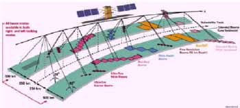
Figure 1, RADARSAT-2 Imaging Modes
The ability to continue to service the existing RADARSAT-1 customers, many of whom have a considerable infrastructure in place, is of utmost importance to the RADARSAT-2 mission. In addition to the new beam modes and features which will be offered by RADARSAT-2, all existing beam modes and product types of RADARSAT-1 will continue to be offered. Table 1 summarizes the beam modes which will be available on RADARSAT-2.
New modes which have been added include multiple polarization imaging capabilities, and Ultra-Fine 3-metre resolution modes. All RADARSAT-1 beam modes will continue to be fully
supported, and for these modes, all RADARSAT-1 image quality specifications will be met or exceeded.
|
with single and dual polarization Transmit H or V Receive H or V or (H and V) |
|
|
|
|
|
|
|
|
| |
|
|
|
|
| |
|
|
|
|
| |
|
|
|
|
| |
|
|
|
|
| |
|
|
|
|
| |
|
|
|
|
| |
|
Transmit H and V on alternate Pulse Receive H and V on every pulse |
|
|
|
|
|
|
|
|
| |
|
|
|
|
|
|
|
Transmit H or V Receive H or V |
|
|
|
|
|
|
|
|
|
4 Spacecraft Characteristics
4.1 SAR Sensor
The RADARSAT-2 SAR antenna will consist of a distributed network of transmit/receive modules arranged on two wings. Some of the SAR characteristics are:
- Linear FM pulse generation with bandwidths from 12MHz to 100MHz;
- Active phased array antenna,16 rows of 32 T/R modules, each feeding a subarray of 20 elements;
- T/R modules with two power settings and temperature compensation of phase and amplitude;
- Each T/R module can transmit either on H or V polarization, and can receive on both polarizations;
- Weighting: phase only on transmit; amplitude and phase on receive;
- Any subset of columns can be switched off on transmit or receive;
- Two independent receive channels used either for H and V polarizations or for separate reception on the leading and trailing antenna wings.
All image data is stored in high data rate (400Mbps) solid-state recorders (SSR). These have higher reliability than tape systems used in the past and will permit random image file access. The SSRs have a capacity of 2 x 128 Gbit at the beginning of the mission, decreasing to 2 x 100 Gbit at the end. They can accept data at rates up to 400 Mbps. Block Adaptive Quantization (BAQ) is used to encode signal data with a selectable wordlength (normally 4 bits I + 4 bits Q). The downlink occurs on two 105 Mbps X-band links. The high-power X-Band transmitter will be able to downlink images to ground stations having a minimum 3-metre receiving antenna.
This smaller antenna size will allow a lower "cost of entry" for new ground stations. Encryption is available for command & control as well as for the downlink of signal data.
4.3 Position Determination
- RADARSAT-2 includes on-board GPS receivers for position determination.
- The absolute position will be determined to within 60m x, y, z 3s in real time on board the spacecraft, to be downlinked with image data. This accuracy will be achieved with the onboard GPS receiver and onboard orbit models.
- The RADARSAT-2 absolute position will be determined to within 15m x, y, z 3s within 24 hours of the latest available GPS orbit data. The GPS receiver onboard will collect position measurements that will be processed on the ground to improve the accuracy.
- RADARSAT-2 is yaw-steered (unlike RADARSAT-1). The yaw steering, combined with the improved attitude control of RADARSAT-2, will simplify image processing and improve image quality.
5.1 UltraFine Imaging Mode
Ultra-Fine mode is designed to provide approximately 3m x 3m resolution images covering swaths of 20km at incidence angles from 30º to 40º.
A pulse bandwidth of 100MHz is used to achieve the required resolution in range. In azimuth a "Dual-Receive" imaging technique is used to achieve the 3 m resolution.
In the Dual-Receive mode of operation, two echoes, one from each wing, are recorded for every pulse transmitted. Because the phase centres of the two receive antennas are in different positions, the two-way path length for the two simultaneous returns are different and so the two returns effectively provide separate samples along the synthetic aperture. With an appropriate choice of PRF, known as the "ideal PRF", the resulting samples will be equally spaced, and standard SAR processing techniques can be employed.
To provide the Doppler bandwidth required to achieve 3m-resolution, an azimuth beamwidth of approximately 0.5º is needed. This is achieved by using a reduced aperture or defocused beam on transmit
In order to improve sensitivity, the T/R modules can be operated at higher transmit power than in the other modes. In addition, the pulse length may be increased. Figure 2 illustrates the Dual-Receive mode of operation. The solid line indicates one pulse transmission with two echoes; the dashed line indicates the pulse and echoes from the next pulse repetition interval.
The Dual-Receive mode is the baseline for Ultra-Fine imaging. However, conventional imaging with a broadened beam (' beam spoiling') was considered as an alternative for Ultra-Fine mode. Dual-Receive mode has the following advantages over beam spoiling:
- better sensitivity for the same power; and
- increased access at high angles because of low PRF.
- some constraints on PRFs; and
- it is unconventional.
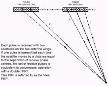
Figure 2, Dual Receive Mode Operation
5.2 GMTI Capability
RADARSAT-2 includes an experimental GMTI capability known as the Moving Object Detection Experiment (MODEX). Like Ultra-Fine mode, MODEX makes use of the Dual-Receive capability of the RADARSAT-2 antenna. This Dual-Receive capability provides two apertures aligned in the along-track direction, which is suitable for detecting moving objects. By processing the received echo data using along-track interferometric techniques and DPCA techniques, objects with non-zero radial velocities can be detected and their radial velocities can be estimated.
6 Ground Segment
To ensure the commercial success of the RADARSAT-2 mission, MacDonald Dettwiler is designing the Ground Segment in consultation with the key organizations and agencies that will be critical to the success of the mission.
Where possible, the existing RADARSAT-1 Ground Segment infrastructure will be re-used. For example the existing TT&C and Data reception facilities will be re-used. For many of the other Ground Segment functions new or upgraded components will be required.
The RADARSAT-2 Ground Segment will provide the following main enhancements to improve the operability and responsiveness to customer needs:
- Reduced mission planning time required for imaging requests. The RADARSAT-2 Ground Segment will be upgraded so that the time between approval of an order and time that the related commands are ready for uplink to the spacecraft is less than 48 hours for routine requests and 6 hours for emergency requests;
- Real-time feasibility checking. When customers' requests for imaging are placed at one of the order desks, the Acquisition and Reception Planning Subsystem will be able to detect conflicts immediately and provide feedback to the customers to assist them in finding feasible imaging times.
- Support for the commercial operations of RADARSAT-2. The ordering and acquisition planning system is being designed to support these operations. The experience gained with RADARSAT-1 operation is being used as a guide.
- Automated data reception and archiving chain. This will allow reductions in time required from image reception to distribution to the customer. After reception of the image data, the Ground Segment will be able to produce and distribute products of any type to the customer within three hours.
- Improved operability and maintainability through the use of MacDonald Dettwiler's standard multi-mission Earth Observation System components, wherever feasible. These same components can be used to build or upgrade network stations for almost every civilian Earth Observation mission.
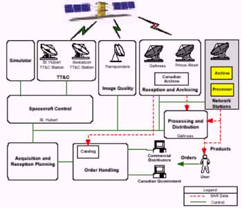
Figure 3, Ground Segment Architecture
7 Development
The companies involved in building the main components of the RADARSAT-2 System are listed below.
- Alenia Aerospazio, Italy is building the spacecraft bus.
- The SAR payload is being constructed by EMS, Montreal (formerly Spar Aerospace).
- The Extendible Support Structure (ESS) is being developed by MD Robotics of Brampton, Ontario.
- In addition to being the mission prime contractor, MDA is also the subcontractor for theGround Segment.
8 References
- Apel John R., McCandless Jr. S. Walter, Reeves L. A., and Valenti E. L., July, 1999. "Application Vistas for RADARSAT-2: Oceans and Ice," IEEE 1999 International Geoscience and Remote Sensing Symposium (IGARSS), Hamburg, Germany.
- Luscombe, A., Oct. 1999. "Plans for Radiometric and Polarimetric Calibration of RADARSAT-2 Beams", CEOS SAR Workshop.
- Luscombe A., Chotoo K., and Huxtable B., July 2000. "Polarimetric Calibration for RADARSAT-2," Proceedings of IGARSS 2000.
- Thompson A. and Livingstone C., July 2000. "Moving Target Performance for RADARSAT-2," Proceedings of IGARSS 2000.