| GISdevelopment.net ---> AARS ---> ACRS 2000 ---> Hyperspectral & Data Acquisition Systems |
Microwave holographic-
imaging remote objects using light-modulated scattering technique
Thammasak
Vimonkiattikun1, Jirawath Panklang2, Anupong
Srongprapa3
1,2Department of Electronic Engineering, Faculty of Engineering
3Applied Microwave Research Laboratory(AMRL)
Department of Applied Physics, Faculty of Science
King Mongkut's Institute of Technology Ladkrabang,
Bangkok 10520,
Tel (66-2)3269980 ext. 213/214, fax: (66-2)3269981,
E-mail: ksanupon@kmitl.ac.th,
Thailand
Keywords: Image Processing, Microwave,
Holography, Digital Signal Processing, Remote Sensing,Modulated
Scattering. 1,2Department of Electronic Engineering, Faculty of Engineering
3Applied Microwave Research Laboratory(AMRL)
Department of Applied Physics, Faculty of Science
King Mongkut's Institute of Technology Ladkrabang,
Bangkok 10520,
Tel (66-2)3269980 ext. 213/214, fax: (66-2)3269981,
E-mail: ksanupon@kmitl.ac.th,
Thailand
Abstract
Modulated scattering technique is mostly used for measuring microwave fields with less perturbation to obtain near - field antenna pattern, such a technique can also be used for microwave holography.A computerized system for recording and reconstruction of microwave hologram at 9.2 GHz X-band frequency is described. A small dipole loaded by MRD 721 photodiode is suspended by thin balsa post at some distance along symmetric Z-axis of the fixed illuminating pyramidal horn antenna. The scattering cross-section of the dipole was modulated by 50 KHz optical signals guided to the diode through a plastic optical fiber. Low-intensity microwave was transmitted to a remote object via a free space and then reflected from object surface. Both the outgoing and backward wave excited the scattering wave, originated from the dipole,then propagated back to the same antenna and mixed with the synthetic off-axis internal reference wave providing by a programmable microwave phase shifter. The object was scanned 1/3 of wavelength stepwise in both X and Y directions, perpendicular to Z-axis, generating 128x128 sampling. For each object position, the output current of the mixer was preamplified and coherently measured at the modulated frequency using a lock-in amplifier to form hologram intensity signals. Fresnel diffraction approximation is used in digital reconstruction from stored hologram data to yield the two- dimensional image of the object.The distance between antenna, scatterer and object plane was allowed to varied. The higher resolving power of system compare with the Rayleigh limit for a conventional hologram has been demonstrated.
1. Introduction
As a mean of seeing through optically opaque medium, various application areas of microwave holography (Tricole,1977) are possible such as all-weather remote sensing, medical diagnosis, buried objects locator, etc. In ordinary system the microwavefield scattered from a stationary object coherently illuminated from a stationary transmitter is mapped over a prescribed hologram recording aperture by means of a detector that is scanned over the aperture. The simplest one need a fixed reference beam to interfere with the object wave and creates wavefield pattern that can be measured by intensity sensitive detector. The more advance one uses coherent phase-locked receiver with local oscillator acting as synthetic internal reference beam. Normally, with regards to the actual size of the conventional probing detector for low intensity application, the detected wavefield is considerably disturbed.
This problem can be overcome by using modulated scattering technique, where the original ones measured the field using a scatterer which may be mechanically (Cullen and Parr,1955), electrically (Richmond,1955) or optically (Iizuka,1963) modulated with synchronous detection of the modulated scattered signal. Orme and Anderson (Orme,1973) used spinning dipole technique of Cullen and Parr in their high resolution microwave holographic imaging of the objects obsured by dielectric media. In the work described here, a system similar to Orme and Anderson's, has been used to perform two-dimensional image of remote metallic objects. Now, the scatterer,in the form of a selected high speed photodiode, is modulated optically via a plastic fiber (Hajnal,1987) and the system is computerized for creating arbitrary internal reference beam angle, scanning control, data collecting and performing image reconstruction digitally.
2. Off-Axis Scanning Source / Receiver Microwave Holography
In some situations where microwavefield can be appropriately described as scalar quantity, scalar diffraction theory of light wave can be used. It is well known in physical optics that light which passes through an aperture or reflects from a plana reflector is fully described by the phase and amplitude distribution in the aperture/or reflector area. According to The Huygens' principle, this is sufficient to reconstruct the light wave at any point behind the aperture (or infront of the reflector). If we describe phase and amplitude in the aperture plane z = 0 by the complex function F(x,y),we obtain for the wave f(x,y,z) which develops behind the aperture (Born and Wolf,1964)
where the symbol * denotes convolution and G is a sperical wave of wavelength originating in the aperture plane. Thus
 with
with  , which becomes in Fresnel's
approximation
, which becomes in Fresnel's
approximation  giving the function
f(x,y,z) to be found from a Fresnel's transform of F(x,y). Figure.1
represents the general geometric set up of the scanning-source/receiver
microwave hologram recording. Here, a point source, a sensor (or
detector), and an object are located at 3 consequetive planes denoted by
source plane, sensor plane and object plane respectively. Spherical wave
emitted from point source at P1 (x,y,z) propagates to a point
P2 (z,h,o) on finite extended object
at object plane. The reflected wave from point P2 propagates to
sensor at position P3 (u,v,w). If sensor and point source are
scanned coincidently,(i.e. x = u , y = v ) the reflected wavefunction at
sensor plane are given by
giving the function
f(x,y,z) to be found from a Fresnel's transform of F(x,y). Figure.1
represents the general geometric set up of the scanning-source/receiver
microwave hologram recording. Here, a point source, a sensor (or
detector), and an object are located at 3 consequetive planes denoted by
source plane, sensor plane and object plane respectively. Spherical wave
emitted from point source at P1 (x,y,z) propagates to a point
P2 (z,h,o) on finite extended object
at object plane. The reflected wave from point P2 propagates to
sensor at position P3 (u,v,w). If sensor and point source are
scanned coincidently,(i.e. x = u , y = v ) the reflected wavefunction at
sensor plane are given by 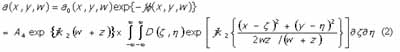
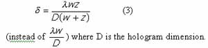
which is recognised as the diffraction field at plane z' = wz /(w+z) distant from the object for the situation of conventional holography. The Rayleigh resolution limit of the system is then given by
At the sensor position there is also reference planewave field b(x,y) whose direction of propagation make an incident angle q to the normal of the plane.Thus
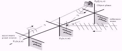
Figure 1. Recording Image data hologram of object using microwave

where a is spatial frequency of wavefront in the x direction which is equal to
 ,
,l = 2p/k is wavelength , and b0 is the field amplitude .
If the total wave function is C(x,y) and regards w as a constant, the intensity at sensor is
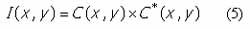


Image reconstruction process concerns with the modification of the reconstructed reference plane wave b*(x,y) by the intensity distribution I(x,y) to be b*(x,y) I(x,y).Fresnel's transform of the term b02a*(X,Y) corresponds to the real image wavefield of the object at the image plane.There is also a direct illuminating field E(u,v,w) which remain constant,as the sensor and source are scanned together.This term do not alter the results derived above significantly.
3. Modulated Scattering Microwave Holographic System
A schematic diagram of the system is shown in Figure 2. Experimental positions arrangement of the pyramidal microwave antenna, dipole scaterrer and object are shown in Figure 3. Both the antenna radiating field and the synthetic off-axis reference wave providing by a programmable movable short phase-shifter are fed by a single 10 mw. 9.2 GHz. Gunn oscillator. Direct illuminating wave and the object wavefield excite the 2 cm.-long MRD 721 photodiode, optically modulated at 50 KHz. via a fiber optic cable, to produce modulated scattering wave travelling back to the same antenna and combines with the reference wave at the mixer. Synchronous demodulation of the mixer signal output after amplification by a low-noise preamplifier is done by using a lock-in amplifier to produce hologram intensity signals. In this computerized-controlled prototype system,the source and scatterrer are stationary while the
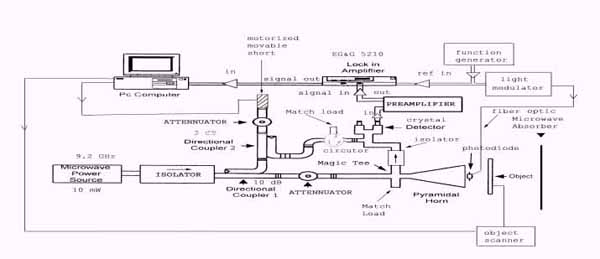
Figure. 2 Schematic diagram of microwave holographic system
object is scanned 1/3 of wavelength stepwise in both x and y direction generating 128 128 sampling signals associate with each position. Fresnel diffraction approximation is used in digital reconstruction from stored hologram data to yield the two-dimensional image of the object.

Figure. 3 Relative position between microwave antenna, dipole and object
4. Experimented Results
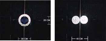
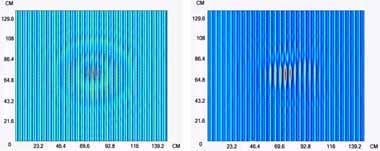
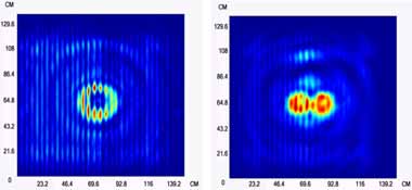
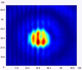
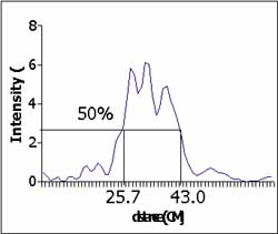
The system was successfully used to image flat metallic objects of various shape and size at different synthesized reference wave incident angle q and limited distance, bound by the size of the existent small anechoic chamber 3.5x3.5x3.5 m3 together with the degrading ratio S/N of the signal, but not too short to violate the Fresnel approximation. Some of the results are shown in Figure 4 for donut-shape object (for z = 288 cm., w = 211.5 cm., q =44.3° ) and dumbbell-shape object (for z = 288 cm., w = 249.5 cm.,q = 44.3° ). Figure 5 shows the full width-half maximum of the image field intensity distribution of a 20 cm. diameter plate (for which z = 288 cm., w = 249.5 cm., q = 44.3°). Consider this case as an example, the theoretical resolution limits are 5.44 cm. and 2.92 cm. for the conventional and source-receiver type hologram respectively. The estimated difference between actual object size and full width-half maximum of 2.7 cm. implies that the resolving power of the system that has been developed is significantly better than conventional system.
(a) (d)
(b) (e)
(c) (f)
Figure. 4 Examples of the experimented results for : (a) donut-shape metallic plate objects with (b) its corresponding microwave hologram.and its image(c), (d) dumbells-shape metallic plate object with (e) its corresponding microwave hologram and its image (f).
 |
 |
| (a) | (b) |
Figure. 5 (a) microwave image of a 20 cm diameter flat metallic plate with (b) its corresponding estimate size from full width-half maximum intensity distribution.
5. Conclusions
A technique for obtaining two-dimensional microwave holographic images of objects using light-modulated scatterer has been described. Images of different target shape using the technique have been presented. The higher resolving power of the system compare with the Rayleigh limit for a conventional holography has been demonstrated.
6. Acknowledgements
The research described in this paper was carried out by the Applied Microwave Research Laboratory, King Mongkut's Institute of Technology Ladkrabang, under a contract with the Thailand National Electronics and Computer Technology Center (NECTEC). We are also grateful for financial assistance from the NECTEC.
Reference
- Born, M., and Wolf, E ., 1964. Principle of Optics., New York.
- Cullen, A.L., and Parr, J.C., 1955. A new perturbation method for measuring microwave field in free space., Proc. IEE, 102B, pp.836-844.
- Hajnal, J.V.,1987., Compound modulated scatterer measuring system., Proc. IEE, 134H(4), pp. 350-356.
- Orme,R.D., and Anderson,A.P., 1973. High resolution microwave holographic technique : application to the imaging of objects obscured by dielectric media., Proc. IEE, 120(4),pp. 401-406.
- Richmond J.H., 1955. A modulated scattering technique for measurement of field distributions. IRE Trans. on Microwave Theory and Techniques., ;V. MTT-3,pp. 13-15.
- Tricoles, G. and Farhat, N. H. , 1977. Microwave holography: applications and techniques, Proc. of the IEEE.,65(1),pp. 108-120.