| GISdevelopment.net ---> AARS ---> ACRS 2000 ---> Digital Photogrammetry |
Automatic acquisition of 3D
spatial data in city with air-borne TLS Three Line Scanner
Yoshiaki KAGAWA and Ryosuke
SHIBASAKI
Center for Spatial Information Science and
Institute of Industrial Science,
University of Tokyo
4-6-1 Komaba, Meguro-ku, Tokyo 153-8505
Tel: 81 -3-5452-6417 Fax 81 -3-5452-6417
E-mail: kagawa@skl.iis.u-tokyo.ac.jp
JAPAN
Key WordsCenter for Spatial Information Science and
Institute of Industrial Science,
University of Tokyo
4-6-1 Komaba, Meguro-ku, Tokyo 153-8505
Tel: 81 -3-5452-6417 Fax 81 -3-5452-6417
E-mail: kagawa@skl.iis.u-tokyo.ac.jp
JAPAN
TLS Three Line Scanner , three-dimensional spatial data, laser scanner , stereo matching,
Abstract
Recently, automatic generation of three-dimensional data in city from aerial images are needed for three-dimensional GIS and revision of GIS database. Though digital or analogue aerial photograph or sequential CCD image data are conventionally used for this purpose, the accuracy and reliability is not sufficient especially for urban area where height of terrain and building surfaces have abrupt changes. Instead, the authors are developing an integrating sensors consisting of three line scanner TLS and laser scanner. TLS is made of three CCD line sensor located in parallel on the imaging plane and has capability of triplet observation, which will have higher accuracy and capability in three-dimensional data generation. By integrating with a laser scanner, reliability of high-resolution three-dimensional city data generation will be improved. In this study, we describe the system configuration and methodology of making three-dimensional data from TLS and the laser scanner using an experimental flight data.
1. Introduction
Recently, three-dimensional data in city are needed, because as compared with two-dimensional data, three-dimensional data can describe detail of city, which enables us conduct more accurate and detailed simulation or analysis on urban areas. Examples of the simulations or analysis are wind simulation around high-rise buildings, fire propagation simulation, flooding analysis and propagation/reflection analysis of electric waves for telecommunication.
Mainly, there are two methods for generation of three-dimensional data. First method is using optical sensor like CCD camera. This method is a successor to traditional analogue aerial photo. But resolution of two dimensional CCD camera is not very sufficient for generating accurate 3D city data generation. Second method is using laser scanner. Laser scanner is an equipment that radiates laser beam to objects and measure distance form the scanner to the object using the return time of the radiated laser beam. When the position of scanner and angle of radiation of laser are known, three-dimensional coordinates of object can be calculated directly. By swinging the laser beam, many data points are obtained, but the resolution is lower than that of CCD sensor. Although studies on application of the individual technologies are conducted, but the possibilities of the combination of both technologies have never been explored using real data. So, in our study, objective is to develop methodology of making three-dimensional data from optical sensor and the laser scanner using an experimental flight data. And as optical sensor, new hardware -Three Line Scanner was used.
2.Three Line Scanner TLS
Three Line Scanner TLS is an optical sensor for aerial survey. Three Line Scanner has three linear CCD located in parallel to get image of three directions -forward, nadir, and backward, which is oriented perpendicular to the flight direction of aircraft. Image is generated due to the aircraft motion by scanning the terrain surface. Fig1

Fig1 : method of getting data with TLS
Differently from CCD frame sensor (two dimensional CCD), the exterior orientation must be computed for each scan-line. The specification of the Three Line Scanner used in this study is shown in Table1. Using linear CCD, the resolution of the image is very high. Single line has 10200 pixels. Ground resolution of the image reaches 5 cm when the flight height is 500m. Flight path and high frequent vibration have a blurring effect on the image, which necessitates the development of stabilizer to absorb the vibration.
| CCD | Number of Pixel/Line | 10200 Pixels |
| Pitch of Pixel | 7 um | |
| Number of CCD | 3 (Monochrome), 1 (RGB) | |
| Number of Shades | (4096 Shades) 12 Bit | |
| Lens | Distance of Focus | 60mm |
| Angle of stereo | 21 ° | |
| Number of Line | 500 Line/Second |
3.Laser Scanner
Data of laser scanner is obtained in a synchronized manner with the TLS. Resolution of data is about 50cm. Fig2 shows data of laser scanner. Location is Roppongi, Tokyo in Japan Ground resolution of the laser scanner data is approximately 50 cm, which is much lower than that of the TLS, though 3D shape of urban objects can be directly extracted from the laser data. But we can know some objects somewhere from data, then they can be used for auxiliary data.
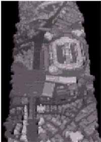
Fig2 : Data of laser scanner seen with bird's eye view
4.Theory
4.1.Posiion and angle data in each line
Flow chart of this study is shown Fig3. First of all, we have to generate accurate data of position and angle in each line. For that, we conducted relative orientation with some ground control points and GPS Global Positioning System /INS Inertial Navigation System data as auxiliary data. From GPS and INS, position and angle of CCD is obtained directly, but the number of measurement per second are lower than the data acquisition frequency of TLS 500Hz , especially GPS data can be obtained only 5 times per second. And data's reliability is not so high, so we use them as auxiliary data.
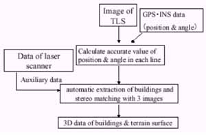
Fig3 : Flow chart of this study
4.2.Automatic extraction of buildings and stereomatching
Fig 4 shows TLS image obtained by a test flight without the stabilizer. Distortions coming from attitude changes of the aircraft prevents the stereo viewing and automatic image matching directly using the raw data. So, we have to rectify these images. For the rectification a horizontal plane located at a mean terrain height is defined. And each pixel of the image is projected on the plane to rectify the distortions.

Fig4 : Raw data of TLS
Fig5 is the rectified image. And then, using the rectified image, buildings are extracted. At first, edges of buildings are extracted from image. With application of wavelet transform, image of edge eliminating noise can be obtained. Then, segmentation is conducted by extracting closed areas. At last, correspondence of an identical object among the three different images are determined in stereo matching process. But there are problems when using only images. For example, wrong correspondence may arise because some buildings may have almost the same characteristics. Another source of wrong correspondence is the occlusion, i.e. a feature in one image may not appear in the other images. Then, in our study, laser scanner data is used for solving these problems.
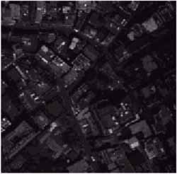
Fig5 : Rectified image of TLS
4.3.Ideas of using laser scanner data to support stereo matching process
Laser scanner data can be used for reducing the range of search for corresponding features area of reference, because the laser scanner data give approximate height of the buildings and terrain surfaces.
And before matching, occluded area can be detected from the coarse 3D data from the laser scanner and the estimated position and attitude of the aircraft. The results of the experiment of integrating TLS data and the laser scanner data will be presented at the conference.
5.Summary
We proposed methodological framework of generating three-dimensional data automatically from data of TLS and laser scanner. For the purpose of generating 3D city model with higher resolution and automation level, TLS image can compensate the low resolution of laser scanner data, while the laser scanner data can assist stereo matching process by providing approximate height of terrain surface and building height. Detailed algorithm should be devised using the experimental flight data. The result will be reported at the conference.
References
- Norbert Haala, Dirk Stallmann and Micheal Cramer, "Calibration of directly measured. position and attitude by aero triangulation of three-line-airbone imagery"
- Ryosuke Shibasaki, 1993, "Three Line Scanner", Photogrametry & Remote Sensing. Vol.32,No.6 pp26-30
- Zhongchao Shi and Ryosuke Shibasaki,1995,"Application of Wavelet Transform Based. Image Segmentation and Stereo Matching for Automated House Detection from Aerial Photograph",Photogrametry & Remoto Sensing Vol.34, No.5