| GISdevelopment.net ---> AARS ---> ACRS 2000 ---> Digital Photogrammetry |
Development of Software to
create a Rectified Image of an Inclined Plane
Ryuji MATSUOKA
Tokai University Research & Information Center
2-28-4 Tomigaya, Shibuya-ku, Tokyo 151-0063, JAPAN
Phone: +81-3-3481-0611, Fax: +81-3-3481-0610
E-mail: ryuji@yoyogi.ycc.u-tokai.ac.jp
Naoki SHIRAI
Department of Research and Development, Kokusai Kogyo Co., Ltd.
2 Rokuban-cho, Chiyoda-ku, Tokyo 102-0085, JAPAN
Phone: +81-3-3288-5921, Fax: +81-3-3262-6150
E-mail: nshirai@kkc.co.jp
KeywordsTokai University Research & Information Center
2-28-4 Tomigaya, Shibuya-ku, Tokyo 151-0063, JAPAN
Phone: +81-3-3481-0611, Fax: +81-3-3481-0610
E-mail: ryuji@yoyogi.ycc.u-tokai.ac.jp
Naoki SHIRAI
Department of Research and Development, Kokusai Kogyo Co., Ltd.
2 Rokuban-cho, Chiyoda-ku, Tokyo 102-0085, JAPAN
Phone: +81-3-3288-5921, Fax: +81-3-3262-6150
E-mail: nshirai@kkc.co.jp
image rectification, digital camera, analytical photogrammetry
Abstract
A piece of software to create a rectified image of an inclined plane for geological survey at a construction site has been developed. The major advantage of our software is that it is easy for a nonprofessional to create a rectified image with sufficient quality.
Digital camera images of an inclined plane are utilized for geological survey at a construction site. A target slope is too large to be covered by one image with sufficient spatial resolution. Not less than several, usually more than ten digital images taken for a target slope should be rectified and connected each other to become an image covering the whole of the target slope. At present each acquired image is manually deformed one by one using a piece of photo-retouch software in PC, and deformed images are also manually connected. This work takes time and quality of the produced image depending on skill of an operator is unsatisfactory in some cases.
Accordingly, we decided to develop a piece of software to create a rectified image covering the whole of an inclined plane in a short time and sufficient quality without ground survey of control points. Our software is based on analytical photogrammetry and image processing technologies, and it is designed for an amateur such as a geological engineer without photogrammetric or image processing know-how to operate it easily after short-period training.
1. Introduction
Photographs of an inclined plane have been utilized for geological survey at a site of a massive scale construction such as dam and highway construction. A lot of analog photographs used to be taken at a construction site. As performance of a digital camera becomes better and its price becomes lower in recent years, digital camera images are becoming major at a construction site.
A digital camera image has several advantages; one is that its quality can be examined immediately after exposure without development, and another is that image data can be transferred directly into a computer. However, a major weak point of a digital camera image is its lower spatial resolution. A target inclined plane is too large to be covered by one image with sufficient spatial resolution. Not less than several, usually more than ten digital images are taken for a target slope. They should be rectified and connected each other to become an image covering the whole of the target slope.
Figure 1 shows a pair of adjacent images of an inclined plane. Each image has a pair of scales on both left and right sides. Though a pair of scales was laid in parallel on the slope, a pair of scales on the image looks not in parallel because a photographer faced obliquely to the target plane. Figure 2 demonstrates a process of creating a rectified image. Each image is deformed and connected each other to become an image covering the whole of the target slope.
At present each acquired image is manually deformed one by one using a piece of photo-retouch software in PC, and deformed images are also manually connected. This work takes time and quality of the produced image depending on skill of an operator is unsatisfactory in some cases. Accordingly, we decided to develop a piece of software to create a rectified image covering the whole of an inclined plane in a short time with sufficient quality.
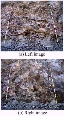
Figure 1 A pair of adjacent images of an inclined plane
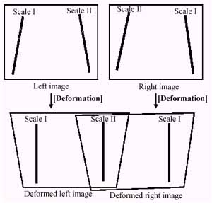
Figure 2 Creating a rectified image of an inclined plane
2. Outline of Developed Software
2.1 User Requirements
User requests to the software to create a rectified image of a slope were summarized as follows:
- Software should be operated easily by an amateur. The software will be operated by a geological engineer or a civil engineer at a construction site who is not used to photogrammetry nor image processing. Software should be operated easily by an operator without photogrammetric nor image processing know-how.
- Field works at a construction site should take a short time. There is a limited time for geological survey at a construction site. No field works except image acquisition are usually allowed at a site. It should be easy for an amateur photographer to take necessary images. No ground survey of control points should be required.
- High spatial accuracy of a rectified image should not be required.A rectified image of a slope will be utilized for visual interpretation. Geological survey at a construction site allows rather lower spatial accuracy of a rectified image.
- No special equipment should be required.The cost of equipment should be low. All hardware components should be inexpensive, and they should be for all purposes and available on the market.
2.2 Processing flow
In order to answer the above mentioned user requests we developed a piece of software to create a rectified image of a slope based on the assumption that the target slope is a plane. Figure 3 shows the processing flow using our software. Outline of each step will be explained in the following section.
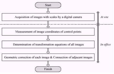
Figure 3 Processing flow using the developed software
2.3 Image acquisition by digital camera
A pair of scales such as staffs in leveling laid in parallel on a target slope is photographed in both sides of an image as shown in Figure 1. This gives geometric controls such as length and straightness in determination of transformation equation of each image. Furthermore this ensures that there is no gap between adjacent images.
Figure 4 illustrates acquisition of a series of images with a pair of scales. Image 1 and Image 3 have Scale I in the left side and Scale II in the right side. In reverse, Image 2 and Image 4 have Scale I in the right side and Scale II in the left side. These movements of Scales I and II are the same as the movements of staffs in leveling.
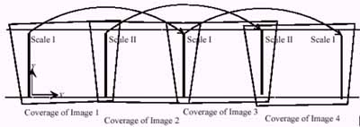
Figure 4 Acquisition of a series of images with a pair of scales
2.4 Measurement of image coordinates of control points
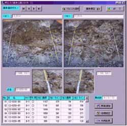
Figure 5 Measurement of image coordinates of control points
Acquired images are transferred into a computer in an office. Two adjacent images are displayed on the computer screen, and an operator clicks at marked points on scales on the screen. Marked points on a scale are treated as control points. Clicked position of each marked point on the image is measured and recorded as image coordinates of the control points. Figure 5 shows a screen for measuring image coordinates of control points. Measurement of image coordinates of control points is the major manual operation of the software.
2.5 Determination of transformation equation
We adopted the following colinearity equation as a transformation equation of a digital camera image:
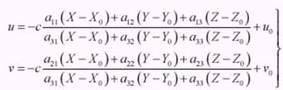
( 1 )
( 2 )
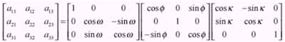
where (X, Y, Z) and (u, v) are the ground and image coordinates of the point respectively, (Xo, Yo, Zo) and (w, f, k ) are position and attitude of the camera respectively, (uo, vo)are the image coordinates of the principal point, and c is the focal length of the camera.
Transformation equations of all images are simultaneously determined by SAPAGO (Simultaneous Adjustment of Photogrammetric And Geometric Observations) developed by the authors. Figure 6 shows geometric constraints of control points used in SAPAGO.
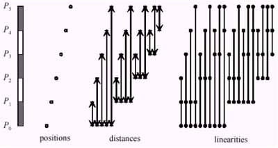
Figure 6 Geometric constraints of control points used in SAPAGO
2.6 Creating a rectified image file
The only work of an operator at this step is to input a size of a pixel of a rectified image to be created. After input of the pixel size of a rectified image a computer executes geometric correction of each image following the determined transformation equation. Finally geometrically corrected images are connected each other to become an image covering the whole of the target slope.
3. Experiment
We conducted an experiment to investigate performance and user-friendliness of the developed software. The objects of the experiment were four excavation slopes at a dam construction site. Widths of the target slopes range approximately from 10 m to 40m and heights of them range approximately from 5 m to 10m. There were three, three, seven and eight images of the target slopes acquired respectively. Each image covers approximately 7 m wide and 6 m high.
Figure 7 shows a rectified image of one of the target slopes made of a series of three images. Figure 8 shows a rectified image of another target slope made of a series of eight images. There are found some discrepancies between adjacent images in both rectified images. The reason of these discrepancies is that a real target slope is not a plane in the strict sense. Since we assumed that the target slope is a plane with the aim of easy operation, these discrepancies are unavoidable. Fortunately these unavoidable discrepancies are negligible for geological survey at a construction site.
There are found another defect that the outermost images (leftmost image and rightmost image) are slightly distorted. The reason of these distortions is that the outermost images are more weakly constrained than the other inside images. Acquisition of images covering the outside of the target slope lets these distortions avoidable.
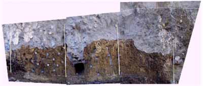
Figure 7 Rectified image of a series of three images
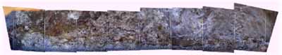
Figure 8 Rectified image of a series of eight images
4. Conclusion
We have developed a piece of software to create a rectified image of an inclined plane for geological survey at a construction site. The major advantage of our software is that it is easy for a nonprofessional to create a rectified image with sufficient quality without ground survey of control points. An operator without photogrammetric nor image processing know-how can operate the software easily after brief training, and create a rectified image of the target slope in a short time with requested quality.
Acknowledgements
The authors are grateful to Mr. Masayoshi Kuji, a geological engineer of Technology Research Institute of Maeda Corporation for his help at the experiment of the software.