| GISdevelopment.net ---> AARS ---> ACRS 2000 ---> Digital Photogrammetry |
Hidden Compensation and
Shadow Enhancement for True Orthophoto Generation
Jiann-Yeou Rau Nai-Yu Chen
Liang-Chien Chen
Tel: 886-3-4227151 Ext. 7651,7627,7622
Fax:886-3-4255535
Center for Space and Remote Sensing Research
National Central University, Chung-Li TAIWAN
Email : jyrau@csrsr.ncu.edu.tw , nychen@csrsr.ncu.edu.tw , lcchen@csrsr.ncu.edu.tw
AbstractTel: 886-3-4227151 Ext. 7651,7627,7622
Fax:886-3-4255535
Center for Space and Remote Sensing Research
National Central University, Chung-Li TAIWAN
Email : jyrau@csrsr.ncu.edu.tw , nychen@csrsr.ncu.edu.tw , lcchen@csrsr.ncu.edu.tw
Hidden and shadow areas are major defects in large-scale aerial photos. Both defects severely degrade the interpretability of orthophotos. Abrupt changes of surface height are the primary sources that cause these defects. Thus, the surface height discontinuities, orientation parameters and solar zenith angle are key factors in determining defect extents. An orthographic rectification scheme minimizing these defects is proposed for generating large-scale true orthophotos. Presuming the DBM (Digital Building Model) and the DTM (Digital Terrain Model) are available, the scheme utilizes projection geometry to detect hidden and shadow areas. For hidden areas, lost information is further compensated with the data from the conjugate image. Seamless mosaic technique considering gray value balance is then applied. For shadow areas, dimmed features are enhanced using local histogram matching method to reduce the impact from poor illumination. Experimental results indicate that the proposed scheme minimizes hidden and shadow defects significantly to generate a true orthophoto using aerial quadruplet.
Keywords
True Orthophoto, DBM, Hidden Compensation, Shadow Enhancement.
1. Introduction
Orthographic rectification process is one important subject in the field of photogrammetry. Despite past achievements, it remains a challenge task to develop an automatic scheme for generating large-scale true orthophotos. First emphasized by Amhar and Ecker [1998], the term "true orthophotos" conceptually refers to ideal orthographic products. The factors considered in relief displacement removal for true orthophoto generation include not only the terrain variation but also canopies. Of which, buildings are often the most important ones.
A complete orthographic rectification task involves two steps of processing, namely, calculating orientation parameters and performing image rectification provided that a surface model is available. With decades of development, calculating orientations for aerial photograph is now a mature technique. Still, new researches are flourishing to extend existing methods and concepts to adapt for carriers and devices of the new age [Chen, et. al 1997]. In the retrieval of surface height information, stereoplotter or analytical plotter is conventionally used for measuring terrain or surface height from stereopair. Meanwhile, various schemes based on patch or feature matching methods have been widely explored to automate height extraction [Chen & Rau, 1993]. To generate digitally true orthophotos, DBM is also needed. Mayer [1999] and Shufelt [1999] surveyed the state-of-the-art automatic building extraction techniques. They concluded that a fully automatic system is still a long way to go. While on the other hand, the importance of semi-automatic approaches is increasingly acknowledged [Sahar & Krupnik, 1999] in a number of applications.
Hidden and shadow areas are major defects shown on orthophotos. Usually, the lager the scale of the orthophoto, the more prominent these defects appear. Both defects severely degrade the interpretability of orthophotos. Abrupt changes of surface height are the primary sources that cause hidden and shadow defects. And for most large-scale orthophoto applications, predominate factors causing surface height discontinuities are buildings. Thus, an orthographic rectification scheme minimizing hidden and shadow defects resulted from buildings is proposed to improve the interpretability for such applications. Fig.1 shows the flow chart of the proposed scheme. A master image is selected from the multi-view image set as the rectification object whereas the others serve as slave images to reimburse for the master image the hidden information. Two major parts are included in the proposed scheme. The orthographic rectification method with hidden detection and compensation is performed first, followed by a shadow area detection and enhancement operation. Section 2 and 3 discuss algorithms for these two parts. A case study presented in section 4 demonstrates the effectiveness of the purposed scheme. Finally, section 5 concludes the discussion.
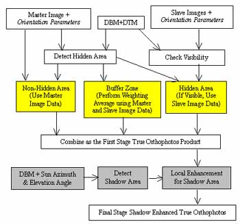
Figure 1, Flow chart of the proposed scheme.
2. Ortho Rectification with Hidden Detection and Compensation
The hidden areas are detected by using Z-buffer and index map. Z-buffer is a matrix set composed of two 2-D matrixes on the image plane. One component of the matrix set is used to record an object location for an image point. The other one stores the distance between the camera and the object and is initialized with a very large value. The index map is also a 2-D matrix on the ground plane to identify if the ground point is hidden. Superimposing DBM on DTM, the coordinates of the surface object may be determined. Applying these coordinates to collinearity condition equation, the projected image coordinates are calculated and rounded to the nearest image grid for each groundel. Meanwhile the projection distance is calculated and compared to the one stored in the Z-buffer. If the distance newly calculated is greater, the corresponding cell in index map is flagged as hidden. On opposite, the location recorded previously is first retrieved from the Z-buffer to locate corresponding groundel for flagging hidden. The Z-buffer is then updated with the new values. As an example, the projection distances of the surface objects X and Z shown in figure 2 are dX and dZ respectively. Because dX < dZ, on index map the cell corresponding to Z will be flagged hidden, and the information regarding X will be stored in the Z-buffer. Since the foregoing detection searches hiddens in horizonal sequence, certain hidden pixels around very steep surface elements may be overlooked. The possibility is illustrated as M portion in fig.2. To solve the problem, along near vertical surfaces pseudo groundels are introduced in the next phase. To determine the number of pseudo pixels, height difference and projection length are used. For instance, if the left building in fig.2 has a height of 50m, the projection length is 5 image pixels, thus on the vertical walls of the building, pseudo pixels are placed in a spacing no greater than 10m. Applying again the detecion rules for these pseudo pixels completes the hidden searching. Due to numerical rounding errors, isolated points or lines may occure in the index map. A post moving window processing employs majority rule to refine the index map is necessary.
With hidden detection mechanism, enhancing orthographic rectification process to minimize hidden defect is possible as shown in fig. 1. Index maps flagging groundels hidden from the master and the slave images is constructed. For each groundel nonhidden from the master image, gray value is casted according to the projection geometry from the master image. For those hidden ones, the index map of slave images are consulted to check for the possibility of patching. Filling-in directly for hidden areas the data patched from slave images may causes radiometric discontinuities. A seamless mosaic technique is developed to reduce the discontinuity. The buffer zone extended from the boundary of particular hidden area is constructed using a morphology operator named dilation. Within the buffer zone, gray value is calculated from both the master and the slave image by weighting average. The weighting factors are determinated according to the distance between the processing pixel and boundary of the hidden area.
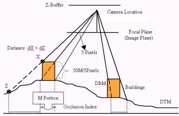
Figure 2, Hidden detection for buildings
3. Shadow Detection and Enhancement Operations
The technique for shadow detection is similar to that for hidden detection. In place of projection geometry, parallel projection is used. The plane of Z-buffer is built perpendicularly to the direction of the sun. In case of lacking such information, this direction may be estimated from the shadow of tall buildings. As shown in fig.3a, the azimuth angle of the sun may be measured from the direction of the shadow, whereas the zenith angle may be calculated from the ratio of the building height to the shadow length. As shown in fig. 3b, the distance stored in Z-buffer is replaced with the path length between the surface object and the local zero height. For convenience, the path length is recorded in negative quantity. Hence, the searching algorithm used for hidden detection may be re-used for shadow detection.
To level the illumination differences around shadow areas, image enhancement technique should be applied. Around the building areas, characteristics of ground features are often dominated by human activities and are usually quite different from place to place. Hence, local enhancement is preferred. Surrounding the shadow area, a buffer zone is first constructed using dilation operator. If presented, rooftops are further excluded from both the shadow area and the buffer zone. This is to keep the similarity of image contents in the shadow area and those in the buffer zone. The histograms for particular pair of buffer zone and shadow area are calculated accordingly. Considering the formal one as the reference histogram, the gray value transformation table for the shadow area is then constructed with histogram matching method. Thereafter, the shadow enhancement may be accomplished area by area.
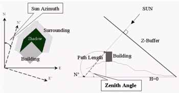
Figure 3, (a) Direction of sun and the buffer-zone surrounding shadow area, (b) Shadow detection, Z-Buffer and path length from local zero height to object.
4. Case Study
To realize the algorithms presented in previous sections, a fully automatic orthographic rectification procedure was developed. Along with the source images, inputs of the procedure include DBM, existing DTM, pre-calculated orientation parameters and direction of the sun. Among the cases studied, the quadruplet covering Fu-Zen University is chosen to illustrate the important features of the proposed scheme. Figure 4 shows the photo data from which the rectangular region highlighted in white box was picked for inspection in the following discussion. The scale of the quadruplet is around , the overlap along and across trip are both about . The photo data was scanned at a spacing of to produce digital images with nominal ground resolution. By assuming the shape of most buildings may be decomposed into vertical walls and horizontal or slant rooftops, the DBM was constructed numerically from coordinates of all building corners measured from analytical plotter.
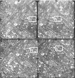
Figure 4, The quadruplet under studying.
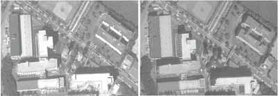
Figure 5,Conventional orthophotos from lower-left and upper-right photo.
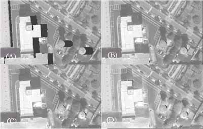
(a) Relief displacement correction only.
(b) Hidden compensation applied without smoothing.
(c) Hidden compensation using seamless mosaic technique.
(d) Shadow enhancement applied.
5. Conclusions
In this study an orthographic rectification scheme is proposed to generate large-scale true orthophotos. Provided that the DBM and DTM are available, the scheme minimizes hidden and shadow defects and improves the interpretability of products. The proposed scheme achieves (1) correction of the relief displacement for buildings and terrain, (2) recovering information within the hidden areas from conjugate photos, (3) stitching filled-in data with master image to reduce discontinuity, and (4) compensating illumination difference for shadow areas. A fully automatic procedure has been developed to examine the proposed scheme. Experimental results indicate that reading barricade is significantly reduced and the products retain good precision and reliability. Though some tuning is needed for processing data other than the aerial photos, a primitive course has been laid in this study for further stepping toward the generation of large-scale true orthophoto.
6. References
- Sahar, L., and A. Krupnik, 1999, "Semiautomatic Extraction of Building Outlines from Large-Scale Aerial Images", PERS, 65 (4), pp.459-465.
- Shufelt, J. A., 1999, "Performance Evaluation and Analysis of Monocular Building Extraction from Aerial Imagery", IEEE Trans. on PAMI, 21 (4), pp.311-326.
- Mayer, H., 1999, "Automatic Object Extraction from Aerial Imagery-A Survey Focusing on Buildings", CVIU, 74 (2), pp.138-149.
- Amhar F., and R. Ecker, 1998, "The Generation of True Ortho-photos Using a 3D building Model in Conjunction with a Conventional DTM", IAPRS, Vol.32, Part4 "GIS-Between Visions and Applications", Stuttgart.
- Chen, N. Y., H. T. Wang and M. M. Lin, 1997, "Orthographic Correction of Airborne Scanner Imagery for Mountainous Areas", Proceeding of the 3rd International Airborne Remote Sensing Conference and Exhibition, held in Copenhagen, Denmark, on 7-10 July, Vol. II, pp. 293-299.
- Chen, L. C. and J. Y. Rau, 1993, "A Unified Solution for Digital Terrain Model and Orthoimage Generation from SPOT Stereopairs", IEEE Trans. on Geoscience and Remote Sensing, Vol. 31, No. 6,pp. 1243-1252.