| GISdevelopment.net ---> AARS ---> ACRS 2000 ---> Digital Photogrammetry |
The Rectification of High
Resolution Remote Sensing Satellite Imagery
Chao-hsiung
WU
Assistant Professor, Digital Earth Research Center
Chinese Culture University
55, Hwa-Kang Road, Yang-Ming-Shan, Taipei 111
Tel:(886)-2-28623538 Fax: (886)-2-28623538
E-mail : chwu@derc.pccu.edu.tw
TAIWAN
Key WordsAssistant Professor, Digital Earth Research Center
Chinese Culture University
55, Hwa-Kang Road, Yang-Ming-Shan, Taipei 111
Tel:(886)-2-28623538 Fax: (886)-2-28623538
E-mail : chwu@derc.pccu.edu.tw
TAIWAN
Remote Sensing Image, Geometric Correction, Ortho-Rectification
Abstract
Since the successful launch of the IKONOS in 1999, its high ground resolution has draw attentions from earth resource management communities. This study involves geometric correction of the IKONOS Geo-product image. Two correction models are applied to the image. 1: without ground control, the relative geometrically corrected image shows a visually acceptable picture. 2: with accurate control points and DEMs' yields ortho-rectified image. The results show that this image can be used for map revision at large and medium scale cost effectively. Further investigation of using satellite onboard data to precisely determine the imaging geometry is recommended.
1. Introduction
Since the advance of earth observation satellites in the late 70's, remotely sensed imagery has been widely used in many fields of earth science. Due to its limited ground resolution, applications in large-scale mapping, planning, zoning and evaluation are not yet readily for business purposes. The successful launch of the U.S. IKONOS in 1999, high ground resolution image is since then commercially available. It provides digital image of 4 meters ground resolution in color and 1 meter in black and white. The revision cycle of 1-3 days makes it possible to periodically monitor the changes of the earth surface in an ever-closer manner. This brings the detailed earth observation scope into a feasible and operational stage that medium/small scale image such as Landsat and SPOT image are not compatible.
The preprocessing of remotely sensed image consists of geometric and radiometric characteristics analysis. By realizing these features, it is possible to correct image distortion and improve the image quality and readability. Radiometric analysis refers to mainly the atmosphere effect and its corresponding terrain feature's reflection, while geometric analysis refers to the image geometry with respect to sensor system.
This paper investigates the geometric characteristics of the IKONOS satellite image. Two scenes were processed and the results were evaluated. Three experiments of various numbers of control points and distribution pattern were conducted to evaluate the planimetric accuracy. The results can be used when this image is to apply at large scale observation and measurement whose geometric requirement is in the order of one meter.
2. Mathematical Model
2.1 Space Transformation
During the satellite imaging process, the projection, the tilt angle, the scanner, the atmosphere condition, the earth curvature and the undulation etc., will cause the satellite image distorted. It is necessary to correction these distortions before one can really use it as a precise measurement in the large scale operations. In this paper, as previously stated, the orbital parameters were unknown. The mathematical model used to compensate the distortion correction is the so-called rubber shifting method. It neglects all the sources of distortions but deal with the present ones with the help of control points. This also makes the correction procedure easier in the circumstance of insufficient parameters. In this study, due to the limitation of the software on hand, one assumption was made in formulating the relationship between image coordinate system and the ground control system. It is assumed that the geometry of the IKONOS imaging system is similar to that of the SPOT, for both scanners are optical system. The import source of the software is image coordinate system. This system is then transform to the photographic coordinate system and again transform to the ground control system.
The transformation model between satellite image coordinate system and the photographic coordinate system is the widely applied Affine transformation or the 6 parameters transformation. The mathematical equation is:
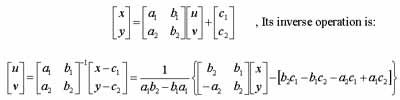
x,y - satellite image coordinates
u,v - photographic coordinate system
a1~c2 - transformation parameters
The model used to link the photographic system to the ground control system is the famous condition: the space resection condition, the co-linearity equation as following:
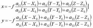
x,y - photographic coordinate, f - focal length
X0,Y0,Z0 - exposure station in ground system
X,Y,Z - control point in ground system a11-a33 - rotation matrix
In a flat terrain, geometric correction can be implemented by transformation of planimetric control points. While in a hilly area, relief displacement of terrain features are significant and need to be compensated. A 3-dimensional transformation should be introduced and the ortho-rectification procedure is adopted.
2.2 Image Resampling
In image resampling, in general, 3 different approaches can be applied, namely: the nearest neighbourhood, the bilinear interpolation and the cubic convolution. They possess their own characteristics but mainly vary in computation time and fidelity. For those who needs more information about resample techniques can refer to interpolation textbooks.
3. Data Source
3.1 Satellite Image
The image used in this study is the IKONOS satellite image. IKONOS was launched successfully on 24 September 1999, from California, USA. The orbit height is 681km above sea level, travel at a speed of 7 km/sec. The revision period ranges from 1 to 3 days depending on the imaging angle. The optical scanner provides image swath of 11km. The sensor system allows simultaneously collection of 1 meter resolution black and white (panchromatic) images and 4 meter resolution color (multispectral) images. The sun-synchronous orbit drive the satellite flies over 24°N latitude at 10:00 a.m. everyday, which allows the image shadows falling onto about the same direction of north-west, and hence improves the efficiency of visual interpretation.
Two IKONOS scenes were used in this paper. The first scene is the forbidden city, Beijin. The imaging date was 10/21/1999 and the data volume is 2006 * 2006 pixels. The second scene is Yuan-shan, Taipei. The imaging date was 10/21/1999, and the data volume is 2101 * 2101 pixels. Both scenes were downloaded from the Internet provided by the Space Imaging Co. Thess image have been radiometrically adjusted to improve the radiometric quality by the producer before uploading to the web site. From a general user point of view, the radiometry can be of little improvement, whilst the geometric accuracy is of concerned as long as the control materials are available. For the second scene, the image frame covers part of northern Taipei area, namely Yuan-shan. The geomorphology in this area is mostly flat terrain, while a small portion of hilly mountain located at the right middle with elevation of 110 meter above sea. Tan-shui river flows through at left of the image and Kee-lung river flows from right middle to north. Highway, metropolitan railway, football field and one of the landmark of Taipei, the Grant Hotel, are clearly visible in this image. Due to the image is an Internet sample, the orbit parameters such as satellite position of exposure, geometry of scanner, tilt angle as well as sun angle are unknown. This makes it impossible to apply orbit parameters in precisely determining the geometry of imaging.
3.2 Control Data
The control data used in this research were derived from two different sources. In the Forbidden City case, due to the lack of ground truth, the control data were read from a 1/15,000 tourism map. It is clear that this map's accuracy is not sufficient for rectification purpose of the IKONOS image. But the geometric condition of the rectangularity for the shape of the Forbidden City was evidently a major constrain from visual inspection of this tourism map. In the Yuan-shan case, a digital 1/1,000 topographic map produced by the Bureau of Urban Development of Taipei City Government was used. It provides approximately 30cm planimetric accuracy and 50cm horizontal accuracy. Compare with the ground resolution of 1 meter of IKONOS image, this digital map provides sufficient control data.
4. Experiences and Results
4.1 Case 1
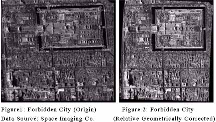
Case 1 refers to the relative geometric rectification of the Forbidden City image. As previously stated, the control points were derived from a tourism map. This map was scanned and converted to a digital form. By superimposing a digital regular grid net on top of the scanned map, relative control points of the test area were derived. In particularly, the right angle corners of the Forbidden City Wall were abstracted and recorded.
Figure 1 shows the original image. It is evident that the corners of the Wall are in skew due to the satellite view angle at the imaging instant. Figure 2 presents the relatively geometric corrected image in which the rectangularity of the Wall corners were maintained.
4.2 Case 2
Case 2 refers to the image rectification with accurate control in various pattern of distribution. Control pattern were classified into 2 types.
The first type is for flat terrain control in which 16 planimetric control points were selected. Among them 9 points served as the control and the rest of 7 points served as the check points.
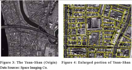
The second test refers to ortho-rectification. The correspondent 1/1,000 digital topographic map was served as the DTM. Figure 3 is the origin scene of Yuan-shan. Figure 4 illustrates a portion of the rectified image in which the digital topographic map is on top of it to provide a visual impression of the processing quality.
All the results in this study are evaluated by the Root Mean Square Error (RMSE) value. Table 1 shows the control pattern and its error vectors using planimetric control. Table 2 shows the RMSE of the ortho-rectification process.
The RMSE of the control points are all less than 1 pixel. The RMSE of the check points are also under 1 pixel in the flat area. While in hilly terrain, the RMSE increase drastically. These results also coincide with the theory that hilly terrain tend to decrease accuracy of height measurement, which shows at point number 15 with tremendous amount of error.
It is clear that after geometric rectification using accurate controls, the IKONOS image can be utilized in large scale mapping and planning. The image in this paper is adopted freely from the Internet and with little knowledge about the satellite attitude during exposure. It is strongly recommended that with the help of orbital parameters, one can expect a reliable and accurate image available for detailed earth observation. The short revision period of this imaging system also provides the possibility of rapid map updating which in general is a time consume and costly task.
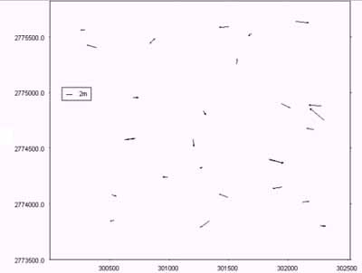
Table 2: The RMSE of control points after ortho-rectification
| Pt # | RMSE | Pt # | RMSE | Pt # | RMSE | Pt # | RMSE |
| 1 | 0.28 | 10 | 0.23 | 4 | 1.4 | 9 | 3.17 |
| 2 | 0.6 | 11 | 0.77 | 6 | 0.76 | 12 | 4.57 |
| 3 | 0.25 | 13 | 0.36 | 7 | 0.43 | 14 | 0.61 |
| 5 | 0.28 | 16 | 0.32 | 8 | 0.58 | 15 | 13.28 |
The images used in this paper are credited to SPACEIMAGING.COM. Thanks to Jen-yu Han, I-hwei Du and Na-wen Tsai for their help in conducting the experiences in this article.
7 References
- Mayr, 1988, ISPRS Congress preceeding, Commission IV, Kyoto, Japan, pp.430-439.
- Lillesand and Kiefer, 2000, Remote Sensing and Image Interpretation, pp.309-438.
- Toutin and Cheng, 2000, Densifications of IKONOS, Earth Observation Magazine, V9, No 7, pp.13-21
- Visser, 1980, Orthophoto Production and Application, The ITC Journal, 1980-4, pp.638-659.
- Wiesel, 1985, Digital Image Processing for Orthophoto Generation, Photogrammetria, 40,pp.69-76.