| GISdevelopment.net ---> AARS ---> ACRS 1999 ---> Topics Including Education |
Development of a Vision-Based
Positioning System for High Density Urban Areas
Tianen Chen and Ryosuke
Shibasaki
Center for Spatial Information Science, University of Tokyo
4-6-1, Komaba, Meguro-Ku, Tokyo 153-8505, JAPAN
E-mail: chen,shiba@skl.iis.u-tokyo.ac.jp
Keywords: High Accuracy Navigation, Mobile
GIS, Image Sequence Analysis, Absolute Orientation, Relative
OrientationCenter for Spatial Information Science, University of Tokyo
4-6-1, Komaba, Meguro-Ku, Tokyo 153-8505, JAPAN
E-mail: chen,shiba@skl.iis.u-tokyo.ac.jp
Abstract
An approach to determine the position and rotation of camera for the purpose of developing Augmented Reality GIS, autonomous navigation systems in urban area is presented in this paper. The method combined CCD camera, DGPS (Differential Global Position System), INS (Inertial Navigation System), magnetometer, gyroscope and image sequence analysis technology. It is also assumed that a 2D/3D GIS (Geographic Information System) of the area is provided. Along street in urban area a sequence of street scene images is captured with CCD camera and matched to the 2D/3D GIS models to determine the system’s positions and orientations constantly. Relative orientation was used to determine the newly captured image’s relative translation and orientation to its predecessor when no models could not be clearly seen from the two neighboring images. The developed methods have been tested with real image and GIS data in outdoor environments. The results indicate that the method is potentially applicable for personal navigation, mobile GIS position, automatic land vehicle navigation in urban area where GPS can not be used smoothly, and Augmented Reality research.
Intruduction
High precise automatic location tracking is a major component for building direction-providing systems, autonomous navigation system, autonomous mobile robots, and Augmented Reality research. For vehicle location, many approaches have been studied and realized before, such as dead reckoning systems, beacon-based navigation systems, radio navigation systems, and GPS. Among those systems, dead reckoning systems are least expensive, but positional errors accumulate and cannot be corrected without other information sources. In fact, dead reckoning is seldom used alone; it is often embedded in other systems, such as beacon-based systems, which have to rely on dead reckoning in areas not covered by beacons. A major problem with beacon-based systems is its high initial cost for installing hundreds or thousands of beacons in a large city and the subsequent cost of maintaining them. Radio navigation systems use radio signals transmitting between fixed stations and vehicles to figure out vehicle locations. For example, some such systems use cellular phone services for signal transmission. The position information provided by current radio navigation systems are not very accurate; average errors may be up to 200 meters. GPS can provide accurate position information for most part of the world, but it may have trouble operating in urban areas where GPS satellite signals are often blocked by high buildings, trees, and other overpasses. We have acquired a DGPS receiver unit and tested it in Tokyo city. We found that the GPS unit was frequently not receiving enough satellite signals to determine the location in 95% areas. Sometimes, GPS did not output any position information for a long time. Also, GPS is not an option for indoor robot navigation.
Another way to acquire position information is by computer vision. In fact, many animals depend on their vision to locate their positions. Vision-based systems are attractive is that they are self-contained, in the sense that they require no external infrastructure such as beacons, radio stations, or satellites. Vision-based systems in principle can operate indoors and outdoors; virtually everywhere as long as there are rich visual features for place recognition.
In this paper, an approach to determine the position and attitude of camera for the purpose of developing AR type GIS and autonomous navigation systems in urban area is presented, which combined CCD camera, GPS, gyro sensor and image sequence analysis technology.
Matching for Image Navigation
Matching is the bottle-neck of landmark-based navigation. It can be defined as the establishment of the correspondence between image-to-model and image-to-image.
Image-to-Model Matching
In most image navigation systems, the key issue is to establish a correspondence between the world model (map) and the sensor data (image). Once such a correspondence is established, the position of vehicle or aerial photograph can be determined easily as a coordinate transformation. In order to solve this problem, we need to extract a set of features from the sensor data and identify the corresponding features in the world model. The problem is further complicated by the fact that the image and the map/model are usually in different formats.
The methods used to match image and 3D models directly can be broadly categorized into three groups: (1) key-feature algorithms, (2) generalized Hough transformation and pose clustering, and (3) tree search.
Unlike these approaches that use the weak perspective approximation, we handle the model-image feature correspondence in tow steps. The first step is to take a second image keeping enough overlaps with the first one and match the two neighboring images with common image-to-image matching methods to be described in next section. The second step is to select line features which are corresponding with landmarks of GIS models from the first image. Since those image line features have been matched with that of the second image. Thus the correspondence between the second image and the 3D models could be indirectly constructed through the first image as their “bridge”. This kind of matching algorithm dose not need any initial estimation values of the camera’s position and rotation.
Image-to-Image Matching
Image matching is one of the most fundamental processes in computer vision and digital photgrammetry. The methods for image matching can be divided into three classes, i.e. area-based matching, feature-based matching, and symbolic (relational) matching (Lemmens, 1988).
Area-based matching is associated with matching gray levels. That is, the gray level distribution of small areas of two images, called image patches, is compared and the similarity is measured by cross-correlation (Lemmens, 1988) or least-squares techniques. Area-based matching require very good intial values for the unknown parameters.
The features used as matching entities in feature-based matching are derived from the original image. In digital photogrammetry, interest points are most often used while in computer vision, edges are preferred. Since edges are more abstract quantities, matching them is usually more robust than matching interest points. The similarity, for example, the shape, sign, and strength (gradient) of edges, is measured by a cost function. Feature-based matching methods are in general more robust and require less stringent assumptions.
The third method, symbolic matching, is sometimes referred to as relational matching, compares symbolic descriptions of images and measures the similarity by a cost function. The symbolic description may refer to gray levels or to derived features. They can be implemented as graphs, trees, or segmentic nets. In contrast to the other methods, symbolic matching is not strictly based on geometric similarity properties. Instead of using the shape or location as a similarity criterion, it compares topological properties.
In our system, the feature-based matching method, combined with the other two matching methods was applied.
Straight line extraction and description
Edges are the most fundamental features of object in the 3D world. Its extraction is important in many computer vision systems since image edges usually correspond to some important properties of 3D objects such as object boundaries. Edges, especially the straight lines, are the main features used in feature-based matching and relational matching. In our method, straight lines are also the main features used to construct the correspondence between 3D models and images. Here, we will briefly introduce their extraction and attribute description for the next matching process.
An edge preserve smoothing filter was used based on Nagao and Matsuyama (1979) which strengthens the gray level discontinuties whilst reducing the gray level differences in homogenous regions. Edges are detected by the convolution of a kernel, or several kernels with the image. Here, the Sobel Operator was preferred. Both edge strength and gradient direction were used to extract straight lines with dynamic programming and lest-square fitting methods at subpixel accuracy (Chen, 1999).
An image line can be described by its attributes, such as position and orientation. These attributes are the most important measures used in image line matching. Besides position and orientation, there are length, contrast, gradient, texture features etc.(Chen, 1999).
Two-step matching
The problem of straight line matching is to find line correspondences over two (or more) images. The similarity of lines in different images is a key feature in matching. In general, relaxation is often used. However, since straight lines have many significant attributes, a more powerful matching function can be defined. As a result, line matching can be a relative single-pass process. In this paper dynamic programming method was used for matching (Chen, 1999).
Matching operation is usually a computationally expensive process. To reduce the cost of computation, a technique of two-step matching is used. In this technique, one first matches a few lines of the orientated image to lines of the unorientated image. This step of the match is called kernel matching, and the line correspondences obtained in this step are called the match base. After kernel matching, a further matching for the remaining lines is performed. In further matching, the matching function is computed with respect to the already matched lines, and therefore the cost of computation is reduced.
Kernel matching.
Kernel matching plays an important role in the whole matching process since the line correspondences obtained from this step will serve as a reference for further matching.
The kernel matching can be formulated as follows:
- Assign unique labels to each line pair with “L” shape junction of the first and the second images.
- Use dynamic programming to find the best match line pair with “L” junction from the second image for each line pair with “L” junction of the first image.
- Compute the orientation disparity. Suppose that n lines in the first
image have been matched with n lines in the second image. The
orientation disparity of the two line subsets can be computed based on
the center point connecting directions. Suppose aij is the direction from the center point
of line Li to that of line Lj in the first image,
bij is the direction determined by
Lki and Lkj in the second image. The orientation
disparity is defined as
dij = | aij - bij | ( 1 )
- Compute the number line’s orientation disparities are smaller than the user defined threshold, and remove those matched lines with lower number from the first and the second images.
- Calculate the position disparities. For a matched line pair
Li in the first image and Lki in the second image,
(xi, yi) and (xki, yki)
denote the center points of them respectively. Thus, two position
disparities in horizontal and vertical directions will be obtained as
- Calculate means and variances of the position disparities. The means
are computed as and the variances as
and the variances as
- Remove those matched lines whose position disparities p and q
satisfy the flowing conditions

or
In the choice of kernel matching lines, the number should be over three. In our experiment, five or seven longest line pairs with highest matching function merits are selected.
After the kernel matching is completed, the correspondences obtained from the match will serve as a reference for the match of the remaining lines. The process of matching the remaining lines based on the already matched lines is called further matching. In further matching, the lines in the first image will be matched one by one, from long to short, to lines in the second. The matching function for further matching are computed with respect to the lines obtained in the kernel matching. Since there are references for the matching, the search range is limited. The criterion for line correspondences is the same as that for kernel matching.
Elimination of conflict matched lines
Mismatching may happen in finding line correspondences. Bidirection matching is an efficient way to limit mismatching. In the process of bidirection matching, matching operations from the first image to the second one and from the second image to the first one are performed. Then line correspondences are confirmed if they exist in both directions of matches. Bidirection matching can usually eliminate most of the mismatched lines although some lines correctly matched only in one direction will also be removed.
Recovering the Position and Orientation of the camera
Absolute Orientation Based on Landmark Line
Fig.2. Geometric Relationship Between 3D Straight Line and 2D Image.
Before discussing the approach to absolute orientation based on landmark lines, we should address that the intrinsic parameters such as focal length, shift of the principle point, distortions of lens, pixel size difference in horizontal and vertical directions, etc. have been correctly determined, the camera should be considered as an ideal pinhole model.
Given a 3D straight landmark line L in the world space and its 2D projection l on the image, a plane through the center of camera S and the two straight lines can be obtained. Fig.2 shows the geometric relationship. Let N be the normal vector of the constructed plan, two geometric constrains are obtained as:
where, Nx, Ny and Nz are the components of N projected on three coordinate axis of the world coordinate system respectively; Xc, Yc, Zc, a,b, and g are the parameters of landmark line in world coordinate system. If more than 3 landmark lines have been matched to the image, the position and orientation of camera could be computed (Chen, 1999).
In the context of landmark-based navigation, it is possible to exploit some of the constraints imposed by the fact that most mobile robots and vehicle navigate on the ground plane in reducing the number of degrees of freedom in the transformation that maps the world model features into the image features. Most positioning tasks make the assumption that the camera is on the ground, so the height of the camera above the ground is assumed to be known or to be a constant. The pitch and roll angles of the camera can be measured with gyro because of its very little drift errors in the tilt and swing angles. So, there are effectively three parameters in the navigation: two translations (Xs, Ys) and one rotation (Yaw angle). This means that only 2D maps or GIS are able to be used to provide landmark information for navigation. So, if more than two straight lines can be extracted from the image and matched with the landmark lines of the map, (Xs, Ys) and Yaw angle of the camera could be calculated. Of course, these lines should be vertical.
For the mismatched lines, an effective approach to detecting blunders was used (Chen, 1999).
Relative Orientation
One of the most obvious characters of mobile robot or vehicle navigation is that the distance from the camera to landmark models in the real world is too near. This will cause very few or even none of any landmark lines could be extracted from the images.
Relative orientation is an effective approach to solve this problem, which describes the relative position and rotation of two neighboring images with respect to one another. It is a 5-parameter problem (see Fig.3). Suppose the position and orientation of one image (camera 1) are known. Based on the image a common coordinate system of the two neighboring images are constructed (Camera1-XYZ in Fig. 3). B denotes the distance between the two image, and is called base-line. Bx, By, and Bz denote the translation of the second image relative to the first one. Yaw, Pitch, and Roll denote the orientation of the second image relative to the first image.
Fig.3. Geometric Relationship of Relative Orientation.
Given a common point P in world space and its two image points in the two image p and p’, whose coordinates in Camera1-XYZ are (X, Y, Z) and (X’, Y’, Z’) respectively, a plane called epipolar plane can be obtained and described as:
To compute the (Bx, By, Bz, Yaw, Pitch, Roll) of the second image, at least five conjugate points from the two images are used. However, since in automatic relative orientation arbitrary conjugate features can be used, the power of redundancy can be readily exploited. Rather than five conjugate points needed to solve the 5-parameter problem, a few hundred points can be used. Due to high redundancy blunders caused by mismatched can be easily detected, and a better point distribution can be obtained. This makes the automatically generated orientation parameters more reliable and more accurate. In addition, the well known dangerous cylinder has no practical significance, since it is virtually impossible for all conjugate points to lie on one of these surface.
Experiment Results
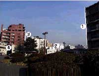
The proposed methods have been tested using various types of images. In this paper, two selected image sequences are used to demonstrate the capacity of the proposed approaches. An imperfect line segment detector is used to extract line segments from the images, with those shorter than 10 pixels being eliminated from the results. The first sequence consists of two images taken with OLYMPUS C141 digital camera in IIS, University of Tokyo in Roppongi, Tokyo city. Fig.4 shows the first image and 4 extracted vertical image lines corresponding with landmark lines extracted from the GIS models of that area. Fig.5 shows another image. To check the accuracy of the positioning, four methods were used: (1) DGPS surveying, (2) DLT (Direct Linear Transform) computation, (3) bundle adjustment, and (4) line-based resection. The landmark points and lines were obtained from 1:500 scale digital maps at 0.3m absolute accuracy provided by Asia Aerial Photogrammetry Company with aerial photogrammetry method. Table1 lists the computed results for the first image with four different positioning methods. Using the indirect image-to-model matching approach presented in this paper, we selected landmark lines from the matching result for the second image (see Fig.5) to compute its position and orientation. Table2 lists the computed results.
 |
 |
Fig.4. The first image and extracted landmark lines. |
Fig.5. The Second image and matched landmark |
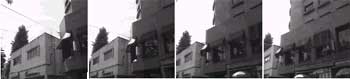
Fig.6.(a) The second image sequence used in our navigation approach
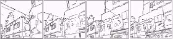
Fig.6. ( b ) Extracted straight lines form the sequence for model-to-image and image-to-image matching.
Table 1. Computed Position and Orientation of Image with Different Methods
|
| ||||
| Measured With GPS & Total-station | DLT | Multi-Photo Bundle Adjustment | Line-Base SR | |
|
| ||||
| Xs | -9339.25 | -9339.77 | -9340.18 | -9339.52 |
| Ys | -37582.16 | -37582.70 | -37582.78 | -37582.64 |
| Zs | 31.69 | 31.53 | 31.42 | ( 31.42 )* |
| Yaw | ---- | 73.3920 | 76.0553 | 75.8456 |
| Pitch | ---- | 103.8135 | 104.3892 | ( 104.82 )** |
| Roll | ---- | 0.8009 | 1.2065 | ( 1.67 )** |
| Points | ---- | 18 | 12 | ---- |
| Lines | ---- | ----- | ---- | 4 |
|
| ||||
** Measured with gyroscope
Table 2. Computed Position and Orientation of Image with Different Methods
|
| ||||
| Measured with GPS & totalstation | DLT | Multi-photo Bundle Adjustment | Line-Base SR | |
|
| ||||
| Xs | -9325.80 | -9325.83 | -9326.07 | -9325.93 |
| Ys | -37580.25 | -37580.85 | -37580.68 | -37580.07 |
| Zs | 32.44 | 32.282 | 32.264 | ( 32.264 )* |
| Yaw | ---- | 71.0708 | 71.3906 | 71.5996 |
| Pitch | ---- | 98.8850 | 97.4843 | ( 97.03)** |
| Roll | ---- | -2.4388 | 0.5695 | ( 0.81 )** |
| Points | ---- | 16 | 12 | ---- |
| Lines | ---- | ---- | ---- | 5 |
|
| ||||
** Measured with gyroscope
Fig.6 shows the second image sequence consisting of four images taken with SONY TRV7 digital video camera along the street of the front gate of IIS, University of Tokyo. The distance between two neighboring images was estimated by walking as 3.5m. The corresponding image points were found by the line matching approach without any information at all. For each pair images more than 100 conjugate points are used to detect the mismatched points effectively with high redundancy. We also computed the relative orientation parameters of these images manually. Table3 lists the computed results. The total computation time for two neighboring images from image capture to the calculation of the relative orientation parameters takes 7 seconds using a Pentium 500 MHz PC.
Table 3. Automatic Relative Orientation Results of the Second Image Seuquence.
| Image Pair | Mean Square Error | m(By/Bx) | v (Bz/Bx) | Yaw (degree) | Pitch (degree) | Roll (degree) |
| 0-1 | Auto 603.7 | -0.4206 | 0.3470 | -2.988 | -1.106 | -1.208 |
| 0.043 | 0.012 | 0.013 | 0.004 | 0.002 | ||
| Manu 754.9 | -0.4193 | 0.3648 | -3.536 | -1.022 | -0.893 | |
| 0.084 | 0.071 | 0.019 | 0.005 | 0.012 | ||
| 1-2 | Auto 699.4 | -0.4734 | 0.2870 | -2.594 | -0.838 | -0.416 |
| 0.029 | 0.015 | 0.009 | 0.003 | 0.003 | ||
| Manu 689.0 | -0.448 | 0.2588 | -3.332 | -0.714 | -0.472 | |
| 0.046 | 0.023 | 0.017 | 0.005 | 0.003 | ||
| 2-3 | Auto 448.8 | -0.4210 | 0.232 | -3.289 | -0.557 | 0.325 |
| 0.028 | 0.010 | 0.009 | 0.002 | 0.001 | ||
| Manu 425.3 | -0.432 | 0.534 | -3.078 | -0.615 | 0.685 | |
| 0.028 | 0.026 | 0.008 | 0.002 | 0.004 |
Conclusion
High precise automatic location tracking is a major component for building direction-providing systems, autonomous navigation system, autonomous mobile robots, and Augmented Reality research. In this paper, an approach to determine the position and attitude of camera using image sequence analysis as the main means was presented in urban area where GPS can not work since the satellite signals are often blocked by high buildings, trees and highways, and disturbed by moving vehicles. We tested the method with real data, and the obtained results show that the method is potentially applicable for personal navigation, mobile GIS position, automatic land vehicle navigation in urban area where GPS can not be used smoothly, and Augmented Reality research.
References
- Chen, T., 1999. Development of High Accuracy Positioning System for Urban Area Using Image Sequence Analysis and Its Application to Augmented Reality in GIS. PhD thesis of University of Tokyo.
- Lemmens, M., 1988. A survey on stereo matching techniques. Int.Arch. Photogramm. Remote Sensing 27(B3), pp.11-23.