| GISdevelopment.net ---> AARS ---> ACRS 1999 ---> Poster Session 5 |
Multi-temporal Cloud Removing
Based on Image Fusion with Additive Wavelet Decomposition
S.Wisetphanichkij, K.
Dejhan, F. Cheevasuvit, S. Mitatha, C.Netbut
Facutly of Engineering and Research Center for Communication and Information Technology,
King Mongkut's Institute of Technology Ladkraband, Ladkrabang, Bangkok 10520,Thailand.
Tel:66-2-3269967, 66-2-3269081, Fax: 66-2-3269086
E-mail: kobchani@telean.telecom.eng.kmitl.ach.th
C.Pienvijarnpong
National Research Council of Thailand
MOS-I Receiving Ground Station, ladkrabang, Bangkok 10520, Thailand.
C. Soonyeekan
Aeronautical Radio of Thailand,
102 Ngamduplee, Tungmahamek, Bangkomk 10120, Thailand
J.Chanwutitum
Faculty of Engineering, King Mongkut's Institute of Technology North Bangkok,
Pibulsongkram Road, Bangkok 10800, Thailand.
AbstractFacutly of Engineering and Research Center for Communication and Information Technology,
King Mongkut's Institute of Technology Ladkraband, Ladkrabang, Bangkok 10520,Thailand.
Tel:66-2-3269967, 66-2-3269081, Fax: 66-2-3269086
E-mail: kobchani@telean.telecom.eng.kmitl.ach.th
C.Pienvijarnpong
National Research Council of Thailand
MOS-I Receiving Ground Station, ladkrabang, Bangkok 10520, Thailand.
C. Soonyeekan
Aeronautical Radio of Thailand,
102 Ngamduplee, Tungmahamek, Bangkomk 10120, Thailand
J.Chanwutitum
Faculty of Engineering, King Mongkut's Institute of Technology North Bangkok,
Pibulsongkram Road, Bangkok 10800, Thailand.
The satellite data image are widely applied such as agriculture, fishery, geology and etc. Although, these data are varied with the time but the data for urban planning and geological data slowly change. The application of multi-temporal satellite image are suitable to study for some cases.
The characteristics of measuring equipment and measured wavelength, especially multi-spectral image such as TM-LANDSAT, OPS-JERS1 image which are applied for visible, infrared and near-infrared range. These waves cannot penetrate through the cloud, thus the data fusion for various times can compensate the lost data.
The multi-spectral image (R,G,B) will be transformed to be HIS (Intensity-Hue-Saturation) component in order to make histogram matching [1] as conventional method. All part of image will be decomposed on wavelet transform [2], the high order coefficients will be combined with the image that contained with cloud for compensation the data of the hidden area.
This paper proposes to use the previous algorithm [3] which allows to use dyadic wavelet to merge the non-dyadic data with a simple and efficient scheme. The results show the preserved and replaced information of cloud removed area on satellite image.
1.Introduction
The remote sensing takes part in the planning and human activities in many fields such as land use in agriculture, fishery geology and urban planning and etc. The limitation of sensor devices according to the wave characteristic of objects and recording signal, transmission ability of the devices, thus the data are specified as shown in Fig.1.
| Satellite image | Resolution (m.) | Number of Band | Cover Area(Km) | Recurrent Period (day) |
| JERS-1 OVN | 18*24 | 4 | 75*75 | 44 |
| Landsat TM | 30*30 | 7 | 184*172 | 16 |
| SPOT PLA | 10*10 | 1 | 60*60 | 26 |
The data fusion technique aids to apply the data with high efficiently and widely used. Although, this data fusion technique is widely used in multi-resolution because there are several situations that simultaneously require the high spatial and high spectral resolution in a single image [1], the data fusionof multi-sensor details of an effective exploiting the complimentary nature of different data type, especially the obtained image from the multi-sensor have the extremely different characteristics [2]. The image fusion of multi-temporal from the Table 1, it is obviously shown that the obtained data from the same area with recurrent period of JERS-1 occurring every 44 days is a long time. Therefore, the applications of multi-temporal image in order to study about the change detection of land cover, which needs the short period less than 44 days. The observed data by using this technique are the observed data are during the required period, the observed data are more ineffective than the previous reason. This paper proposes a technique for cloud removing by using a fusion of multi-temporal removing by using a fusion of multi-temporal image, both original images are prepared for geometric correction by using ground control point. Then, the multi-spectral image (R,G,B) will be transformed to be HIS (Intensity-Hue-Saturation) component in order to make the histogram matching [4] as previous mentioned. The images after passing the brightness correction will be fused by using the additive wavelet decomposition technique in order to have a small effect with the original data.
2.Image preparation
Both original images will be processed in order to have geometric correction by assigning the ground control points and bi-cubic polynomial fit. Both images in RGB color space are transformed to the HIS component, however HIS transformation algorithm have been developed for converting the RGB values. While the complexity of the models varies, it produces the similar value for H (Hue) and S (saturation) [3]. The algorithms have the different method to calculate the component of I (intensity) [1].
The brightness of both images should be matched before fusing. To calibrate the brightness, the intensity component of the other image to be used as reference. The mean and standard deviation of each image can be calculated, these values are used to adjust the brightness of an image to the other reference image. The expression can be written [4] as follow,
I': calibrated value.
m1, s1 reference values of brightness mean and standard deviation, respectively.
m2, s2 reference values of mean and standard deviation of image under consideration, respectively.
Both images will be inversely transformed to be the RGB space after adjusting the brightness, then the equation (4) can be rewritten as follows.
The corrected geometrical images after passing the brightness adjust is shown in Fig.1.
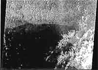
(a) JERS-OPS (Feb. 28,1998)
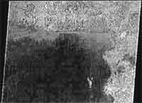
(b)JERS-OPS (Apr. 13,1998)
Fig.1. Corrected geometrical images (a).cloud-covered image (b). cloud-free image
3.Wavelet Decomposition
The wavelet decompositoon is widely used for image processing. The proposed method is based on the image decomposition into multiple-channel depending on their local frequency content. The wavelet transform provides a framework to decompose image into a number of new images, each of them has a different degree of resolution. As the Fourier transform gives an idea of frequency content for image, the wave representation is an intermediate representation between Fourier and spatial representations. It is able to provide the good localization for both frequency and space domains. The wavelet transform of a distribution f(t) can be expressed as follows.
As a and b are scaling and translation parameters, respectively. Each base function ((t-a)/b) is a scaled and translated version of function called other wavelet. These base functions are ò y((t-a)/b)=0.
The discrete approach of the wavelet transform can be done with several different algorithms. To obtain a shift-invariant discrete wavelet decomposition of image. The previous paper [1] proposed to use the wavelet transform algorithm to decompose the image into wavelet planes.
F1(P) = P1 ; F2(P1) = P2 ; F3(P2) = P3; ... (8)
To construct the sequence, this algorithm performs successive convolutions with a filter obtained from auxiliary scaling function. The use of a B3 cubic spline leads to be a convolution with 5*5 mask.
 (9)
(9) The wavelet planes (W1) are computed as the difference between two consecutive approximation pI-1 and P1.
As, P1 are versions of original image P at increasing scales.
W1 are multi-resolution wavelet planes. 0
Pr is a residual image
4. Methodology and result
Because of continuously and evidently appear in white color of cloud, these attributes will found in both spectral and spatial domains. Otherwise, the shadow of cloud appears in black color. To remove the cloud and its shadow in effectually, the gray level slicing merged as shown in Fig.2.
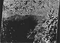
Fig.2. The clouded image, after passing the gray level slicing process.
The continuity of cloud and its shadow will be separated and removed from the other data with wavelet decomposition techniques as mentioned above and shown in Fig.3. In other to compensate removed data, the low-resolution component of the cloud-free image (P'r) will be added to the residual component of cloud removed image as shown in Fig.4.
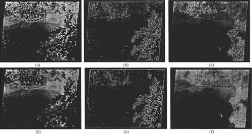
Fig 3. The wavelet decomosed image (a), (b) low-frequency and high-frequency term of clouded image (c) low-frequency term of cloud-free image with n=1, and (d),(e) and (f) for n=3, respectively.
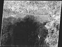
Fig. 4. Result form cloud removing after fusing the low and high frequency components.
In Fig.4, the cloud-covered data can be replaced. The low frequency component has no cloud or cloud-free, it can maintain the data which is the high frequency component (P'). these data are needed to keep. To get rid of the cloud edge can be done by applying the image data to the low-pass filter but some data will be lost.
5. Conclusion
The proposed technique in this paper can improve the cloud covered image data. The lost data compensation by fusing with wavelet decomposition, the data may be the same region of area, different time, and different sensor. The collected data depend on the scaling index (n). the selection of scaling index depends on type and quantity of covered cloud. Although, the proposed technique con not compensate all data but this technique is simple and easy to apply.
6. References
- J. Nunez, X. Otazu and R. Ardiol, "Multiresolution-Based Image Fusion with Additive Wavelet Decomposition," IEEE Trans. Geoscience and Remote Sensing, Vol. 37, No. 3, pp. 1204-1211, May 1999.
- Y.C.Liao, T.Y. Wang and W.T. Zheng, "Quality Analysis of synthesized High-Resolutin Multispectral Imagery, " proc. 19yh Asian conference on Remote Sensing, pp. I-1-1 -I-1-6, Nov. 16-19,1998.
- R.C. Gonzaley and R.E. Woods, Digital Image Processing, Addition-Wesley Publishing Company, USA, Sep. 1993.
- F.Cheevasuvit, C. Peanvijarnpong and S. Murai, "Mosaicing of poor contrast images," proc. 9th Asian conference on Remote Sensing, pp. H-1-1-1 - H-1-1-9, Nov. 26-29, 1998.