| GISdevelopment.net ---> AARS ---> ACRS 1999 ---> Poster Session 4 |
The Making of High Precision
Orthoimage of Ancient Buildings
Jiang Wanshou, Zhu Yixuan
(School of Information Engineering, WTUSM,
129 Luoyu Road, Wuhan, China, 430079)
(School of Information Engineering, WTUSM,
129 Luoyu Road, Wuhan, China, 430079)
Key Words: orthoimage, DEM, hiding relation,
visibility, context mapping
Abstract
Traditionally, orthophotos or orthoimages are made on the base of regular grid DEM, which implies that the terrain surface is smooth. But as for close range photographs of buildings, the hypothesis of smoothness is no longer right. And the hiding relations between object surfaces exist here and there. This paper puts forward a method of producing accurate orthoimage of buildings, which is based on TINs and context mapping. With this method, hiding relation can be considered exactly and relative constrain conditions can be included. An orthoimage software-WuTINOrtho, which will be a module of VirtuoZo, has been developed
1. Introduction
Orthophotos are important products of photogrammetry. The making of orthophoto is a complex procedure. At the era of analytical photogrammetry, people make orthophotos with orthophoto projector such as Avioplan OR-1. OR-1 adopts strip-scanning method to produce orthophotos, in which the zoom factor and rotating angle of Dove are controlled according to the DEM data. The principle of OR-1 determines the DEM must be regular grids. However, regular grids can not represent accurate object surfaces and hiding relations between object surfaces, which are very important for making orthophotos of large-scale buildings. In fact, the problem also exists when making orthophotos of large-scale urban areas. Just for that the scale of aerial photographs is not too large, the displacements of building roof can be tolerated.
The development of digital photogrammetry and the advantage of digital orthophoto provide a possibility to overcome the problem. The digital orthophoto is also called virtual orthophoto or orthoimage. When making orthoimages, point-wise processing mode is better than the strip-wise mode in analytical photogrammetry, for the displacement and visibility of image points can be considered point by point.
In close range photogrammetry of buildings, the geometric relations between buildings are very complicated. There exist not only breaking in depth direction but also complicated hiding relations. As shown in Fig.2.there are three surfaces.the two convex surface hide other surfaces. In order to make high precision orthoimage, the surfaces have to be measured exactly, and the orthoimage should be generated with context mapping method. The pixels should be resampled on best photo. When generating orthoimage, not only the visibility in ortho direction but also the visibility in projective direction of photographs must be taken into account. Generally speaking, the making procedure of high precision orthoimage can be described as Fig.1:
Fig.1 The making procedure of close range orthoimage
The First step is orientation of photos, including interior orientation and exterior orientation, providing the conditions of reconstructing the ray bundles of photographing. If only one photo or only one stereo module is adopted, orientation is not a big problem. But when making a big orthoimage, in which more than one photos or stereo models have to be adopted, the precision of orientation can be a big problem, because any small difference of orientation can be visible in the overlapping area in mosaic image.
Triangle is the simplest data structure, which is also most flexible. Triangles or TIN can represent object surfaces in any precision. A TIN can represents a smoother surface. And several TINS can represent disconnected surfaces.
In order to consider the hiding relation between surfaces the depth maps of orthoimage and original images must be generated. When generating orthoimage, only surface point whose depth is not larger than the depth of orthoimage depth map be generated. On the other hand, because every orthoimage point can be projected onto all images, that on which image the destination pixel value should be resampled is a key problem.
In close range photograph of building, dead angles are inevitable, which appear as blank area on orthoimage. So orthoimage have to be fixed with image processing software such as Photoshop. With Photoshop, we can also adjust the image level or even change the color of the image.
2.The representatives of object surface
Considering the complexity of the processed buildings, we adopt two kinds of data structure to represent the surfaces of the building. Being a single valued function, it’s difficult for 2D TIN to express the breaking and hiding relation of multiple surfaces. So, we adopt multiple TINs to express disconnected surfaces. As for some more complex surfaces, such as cylinder, sphere etc, we use a series of triangles to express them. As shown in Fig.2, the surface in Z direction can not be a part of a TIN.
Fig.2 Hiding and visibility
In order to express surfaces exactly, the constraints of edge between surfaces must be taken into account. The constrained TIN generator we use is a shared program by Jonathan Richard Shewchuk.
3.The building of depth map image
Depth map in ortho direction is relatively simple. It’s a rasterization processing for every triangle. The depth of raster point can be interpolated linearly. But the depth maps of original photos are very different. As we know, projective transformation is nonlinear, the depth of raster point can not be interpolated linearly. On original photos, the depth of raster point has to be computed according to the object space coordinates. As shown in fig.3.the ray Sp can be expressed as EQ.1.the plane P1P2P3 can be expressed as EQ.2. The intersection point P(X,Y,Z) of ray Sp and triangle P1P2P3 can be solved from equations EQ.1 and EQ.2.
Fig.3 Intersection of ray and triangle
depth = (Z max - Zp) * depthScale (4)
The resolution of depth maps can not be lower than the resolution of processed images. And the range of depth maps can be determined according to the range of surfaces data. Considering the conflicts between the precision and the memory needs, we choose a WORD (unsigned short integer, whose size is two bytes) to express the depth. The range of WORD is between 0 and 65535. The depth value of every point can be map into the range with EQ4. The depth scale can be computed with EQ.3.
4.Visibility judgement and orthoimage generating
When generating orthoimage, triangles are scanned one by one, depth of every raster point are computed according to EQ.4. If the depth is not larger than the depth registered on ortho depth map, then the point is visible. The pixel value of the point has to be resampled on the photo on which the point is both visible and nearest to the projective center.
Different from general hiding processing, the point projected from ortho image seldom happened to be on the pixel center of original images. Therefore, not only pixel values but also depth values need to be interpolated. Pixel value can be interpolated with bilinear interpolation or bicubic convolution. But depth values can not be interpolated simply according to the neighboring depth values, for the non-linearity of projective transformation. Fortunately, we can turn to the visibility of the neighboring pixel. That is to project neighboring pixel onto the currently processed triangle, if the depth of projective point is not larger than the depth value of depth map, then the neighboring pixel is visible. If every neighboring pixel is visible, the interpolated point is also visible on the image. Otherwise, if the point is near the edge, then if more than two neighboring pixels are visible, then we say the point is also visible.
5. Experiment
Based on the current version of VirtuoZo, the author has made a program on SGI Indigo2, which we call WuTINOrtho. With WuTINOrtho, we have produced the ortho image of the Main Hall of the Chi Lin Nunnery, which is one of the ten famous scenes in Hongkong.
Shown in fig.4 are five photos of the Main Hall, which is photographed by WILD P31 and scanned by Vexcel 3000. The scanning resolution is 0.020mm. The principal distance f is 9.66mm. Viewed from the front, the visible width of the building is about 33 m, the height is about 17m, and the depth is about 17m. The largest photographing distance is about 27m, and the smallest distance is 10m.
Table 1. The precision of inner orientation
Table2 The precision of relative orientation
Table3 The precision of absolute orientation
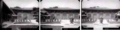
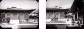
Fig.4 Five Photos of the Main Hall of Chi Lin Nunnery
After orientation, we measured the front surfaces of the building with VirtuoZo digitizing program. For some part such as pillar and tiling, the data measured in filed are adopted. In addition, some relative constraints of the building itself are included.
Left Part of fig.5 is the map of incense burner and grades, the right part are their orthoimage. Their scale is 1:50. On the original images, the scale of the incense burner is much larger than the scale of grades, and the incense burner hides large part of the grades. After ortho rectifying, their scale is changed to 1:50. The hidden part of the grades is resampled from other images.
As for the blank area caused by the dead angle of photographing, they are fixed with Photoshop.
6.Conclusion
From this experiment, we can say, the orthoimage making program WuTINOrtho, which is based on the current version of VirtuoZo digital photogrammetry system, is practicable, the algorithm in which multiple levels of TINs, hiding relation reconstruction and context mapping technique are included is feasible for close building photogrammetry.
Making close range building orthoimage requires multiple stereo models, accurate orientation results and geometry data, high-resolution images, and taking relative constraints into account.
The digitizing of object surface is a key step, which costs most time. For the ancient building such as the Chi Lin Nunnery, the image matching result is still unacceptable. And the manual measurement of them is also difficult. In the future, more research should be focused on the automatic data acquirement from the images of close building, in which object model, context pattern, relative conditions can be considered.
Reference
Abstract
Traditionally, orthophotos or orthoimages are made on the base of regular grid DEM, which implies that the terrain surface is smooth. But as for close range photographs of buildings, the hypothesis of smoothness is no longer right. And the hiding relations between object surfaces exist here and there. This paper puts forward a method of producing accurate orthoimage of buildings, which is based on TINs and context mapping. With this method, hiding relation can be considered exactly and relative constrain conditions can be included. An orthoimage software-WuTINOrtho, which will be a module of VirtuoZo, has been developed
1. Introduction
Orthophotos are important products of photogrammetry. The making of orthophoto is a complex procedure. At the era of analytical photogrammetry, people make orthophotos with orthophoto projector such as Avioplan OR-1. OR-1 adopts strip-scanning method to produce orthophotos, in which the zoom factor and rotating angle of Dove are controlled according to the DEM data. The principle of OR-1 determines the DEM must be regular grids. However, regular grids can not represent accurate object surfaces and hiding relations between object surfaces, which are very important for making orthophotos of large-scale buildings. In fact, the problem also exists when making orthophotos of large-scale urban areas. Just for that the scale of aerial photographs is not too large, the displacements of building roof can be tolerated.
The development of digital photogrammetry and the advantage of digital orthophoto provide a possibility to overcome the problem. The digital orthophoto is also called virtual orthophoto or orthoimage. When making orthoimages, point-wise processing mode is better than the strip-wise mode in analytical photogrammetry, for the displacement and visibility of image points can be considered point by point.
In close range photogrammetry of buildings, the geometric relations between buildings are very complicated. There exist not only breaking in depth direction but also complicated hiding relations. As shown in Fig.2.there are three surfaces.the two convex surface hide other surfaces. In order to make high precision orthoimage, the surfaces have to be measured exactly, and the orthoimage should be generated with context mapping method. The pixels should be resampled on best photo. When generating orthoimage, not only the visibility in ortho direction but also the visibility in projective direction of photographs must be taken into account. Generally speaking, the making procedure of high precision orthoimage can be described as Fig.1:
Fig.1 The making procedure of close range orthoimage
The First step is orientation of photos, including interior orientation and exterior orientation, providing the conditions of reconstructing the ray bundles of photographing. If only one photo or only one stereo module is adopted, orientation is not a big problem. But when making a big orthoimage, in which more than one photos or stereo models have to be adopted, the precision of orientation can be a big problem, because any small difference of orientation can be visible in the overlapping area in mosaic image.
Triangle is the simplest data structure, which is also most flexible. Triangles or TIN can represent object surfaces in any precision. A TIN can represents a smoother surface. And several TINS can represent disconnected surfaces.
In order to consider the hiding relation between surfaces the depth maps of orthoimage and original images must be generated. When generating orthoimage, only surface point whose depth is not larger than the depth of orthoimage depth map be generated. On the other hand, because every orthoimage point can be projected onto all images, that on which image the destination pixel value should be resampled is a key problem.
In close range photograph of building, dead angles are inevitable, which appear as blank area on orthoimage. So orthoimage have to be fixed with image processing software such as Photoshop. With Photoshop, we can also adjust the image level or even change the color of the image.
2.The representatives of object surface
Considering the complexity of the processed buildings, we adopt two kinds of data structure to represent the surfaces of the building. Being a single valued function, it’s difficult for 2D TIN to express the breaking and hiding relation of multiple surfaces. So, we adopt multiple TINs to express disconnected surfaces. As for some more complex surfaces, such as cylinder, sphere etc, we use a series of triangles to express them. As shown in Fig.2, the surface in Z direction can not be a part of a TIN.
Fig.2 Hiding and visibility
In order to express surfaces exactly, the constraints of edge between surfaces must be taken into account. The constrained TIN generator we use is a shared program by Jonathan Richard Shewchuk.
3.The building of depth map image
Depth map in ortho direction is relatively simple. It’s a rasterization processing for every triangle. The depth of raster point can be interpolated linearly. But the depth maps of original photos are very different. As we know, projective transformation is nonlinear, the depth of raster point can not be interpolated linearly. On original photos, the depth of raster point has to be computed according to the object space coordinates. As shown in fig.3.the ray Sp can be expressed as EQ.1.the plane P1P2P3 can be expressed as EQ.2. The intersection point P(X,Y,Z) of ray Sp and triangle P1P2P3 can be solved from equations EQ.1 and EQ.2.
Fig.3 Intersection of ray and triangle
where,
(X, Y, Z) = intersection of ray Sp and triangle P1P2P3
(Xi, Yi, Zi) = vertices of triangle P1P2P3
(Xs, Ys, Zs,) = projective center S
l = photoscale
(x, y) = photo point
f = principal distance
(X, Y, Z) = intersection of ray Sp and triangle P1P2P3
(Xi, Yi, Zi) = vertices of triangle P1P2P3
(Xs, Ys, Zs,) = projective center S
l = photoscale
(x, y) = photo point
f = principal distance
depth = (Z max - Zp) * depthScale (4)
where:
depthScale = depth scale from actual depth to the range of WORD
Zmin = the minimum Z coordinate of objects
Zmax = the maximum Z coordinate of objects
Zp = the coordinate of object point P
depth = the depth of Point P in WORD range
depthScale = depth scale from actual depth to the range of WORD
Zmin = the minimum Z coordinate of objects
Zmax = the maximum Z coordinate of objects
Zp = the coordinate of object point P
depth = the depth of Point P in WORD range
The resolution of depth maps can not be lower than the resolution of processed images. And the range of depth maps can be determined according to the range of surfaces data. Considering the conflicts between the precision and the memory needs, we choose a WORD (unsigned short integer, whose size is two bytes) to express the depth. The range of WORD is between 0 and 65535. The depth value of every point can be map into the range with EQ4. The depth scale can be computed with EQ.3.
4.Visibility judgement and orthoimage generating
When generating orthoimage, triangles are scanned one by one, depth of every raster point are computed according to EQ.4. If the depth is not larger than the depth registered on ortho depth map, then the point is visible. The pixel value of the point has to be resampled on the photo on which the point is both visible and nearest to the projective center.
Different from general hiding processing, the point projected from ortho image seldom happened to be on the pixel center of original images. Therefore, not only pixel values but also depth values need to be interpolated. Pixel value can be interpolated with bilinear interpolation or bicubic convolution. But depth values can not be interpolated simply according to the neighboring depth values, for the non-linearity of projective transformation. Fortunately, we can turn to the visibility of the neighboring pixel. That is to project neighboring pixel onto the currently processed triangle, if the depth of projective point is not larger than the depth value of depth map, then the neighboring pixel is visible. If every neighboring pixel is visible, the interpolated point is also visible on the image. Otherwise, if the point is near the edge, then if more than two neighboring pixels are visible, then we say the point is also visible.
5. Experiment
Based on the current version of VirtuoZo, the author has made a program on SGI Indigo2, which we call WuTINOrtho. With WuTINOrtho, we have produced the ortho image of the Main Hall of the Chi Lin Nunnery, which is one of the ten famous scenes in Hongkong.
Shown in fig.4 are five photos of the Main Hall, which is photographed by WILD P31 and scanned by Vexcel 3000. The scanning resolution is 0.020mm. The principal distance f is 9.66mm. Viewed from the front, the visible width of the building is about 33 m, the height is about 17m, and the depth is about 17m. The largest photographing distance is about 27m, and the smallest distance is 10m.
| Precision\photo | DX12 | DX13 | DX14 | DX15 | DX16 |
| Mx(mm) | 0.026 | 0.001 | 0.003 | 0.003 | 0.010 |
| My(mm) | 0.004 | 0.004 | 0.002 | 0.002 | 0.002 |
Table2 The precision of relative orientation
| Precision\model | DX12-13 | DX14-15 | DX15-16 |
| Mq(mm) | 0.004 | 0.004 | 0.003 |
Table3 The precision of absolute orientation
| precision\model | DX12-13 | DX14-15 | DX15-16 |
| Mx(cm) | 0.68 | 0.42 | 0.67 |
| My(cm) | 0.56 | 0.52 | 0.50 |
| Mz(cm) | 0.70 | 0.53 | 0.35 |
Fig.4 Five Photos of the Main Hall of Chi Lin Nunnery
 Fig.5 pictures of incense burner and grades |
 Fig.6 Orthoimage of the Main Hall |
After orientation, we measured the front surfaces of the building with VirtuoZo digitizing program. For some part such as pillar and tiling, the data measured in filed are adopted. In addition, some relative constraints of the building itself are included.
Left Part of fig.5 is the map of incense burner and grades, the right part are their orthoimage. Their scale is 1:50. On the original images, the scale of the incense burner is much larger than the scale of grades, and the incense burner hides large part of the grades. After ortho rectifying, their scale is changed to 1:50. The hidden part of the grades is resampled from other images.
As for the blank area caused by the dead angle of photographing, they are fixed with Photoshop.
6.Conclusion
From this experiment, we can say, the orthoimage making program WuTINOrtho, which is based on the current version of VirtuoZo digital photogrammetry system, is practicable, the algorithm in which multiple levels of TINs, hiding relation reconstruction and context mapping technique are included is feasible for close building photogrammetry.
Making close range building orthoimage requires multiple stereo models, accurate orientation results and geometry data, high-resolution images, and taking relative constraints into account.
The digitizing of object surface is a key step, which costs most time. For the ancient building such as the Chi Lin Nunnery, the image matching result is still unacceptable. And the manual measurement of them is also difficult. In the future, more research should be focused on the automatic data acquirement from the images of close building, in which object model, context pattern, relative conditions can be considered.
Reference
- Wang Zhizhuo.Principles of Photogrammetry with Remote Sensing. Press of Wuhan Technical University of Surveying and Mapping, 1990
- Zhang Zuxun, Zhang Jianqing, Digital Photogrammetry.Press of Wuhan Technical University of Surveying and Mapping, 1997
- Jonathan Richard Shewchuk.Triangle: Engineering a 2D Mesh Generator. http://www.cs.cmu.edu/~quake/triangle.html
- 4. David F. Rogers, Procedural Elements for Computer Graphics, McGraw-Hill, Inc., 1983