| GISdevelopment.net ---> AARS ---> ACRS 1999 ---> Poster Session 3 |
Update of GIS data by using
simple type mobile interface system
Osamu Akutsu*, Ryosuke Shibasaki**, Bokuro Urabe*
*Geographical Survey Institute, Ministry of construction
**Center for Spatial Information Science, University of Tokyo
1 Kitazato, Tsukuba, Ibaraki 305-0811, Japan
Tel: 81-298-64-5913 Fax: +81-298-64-3056
E-Mail:akutsu@gsi-mc.go.jp
Osamu Akutsu*, Ryosuke Shibasaki**, Bokuro Urabe*
*Geographical Survey Institute, Ministry of construction
**Center for Spatial Information Science, University of Tokyo
1 Kitazato, Tsukuba, Ibaraki 305-0811, Japan
Tel: 81-298-64-5913 Fax: +81-298-64-3056
E-Mail:akutsu@gsi-mc.go.jp
Background
In recent years, the use of Geographic Information System (GIS) is increasing rapidly among the various fields and users, such as the government, corporations, and general users. In such a circumstance, GSI should provide geographic data not only in raster-base but also in vector-base.
Purpose
It needed time and labor to acquire the position data in 2 dimensions or 3 dimensions. Recently, using an electronic flat board and GPS, real-time GIS data acquisition has become available. However, since it is using GPS, this system is quite expensive, and data acquisition is almost impossible in urban area.
Considering the situation above, it is necessary to develop economical simple-type Mobile interface system, which can easily and rapidly acquire GIS data in such urban area.
Figure 1 Data acquisition flow
Contents
The author develop a system to take data from lasers, magnetic azimuth sensors, gyro sensors and GPS into the personal computer (PC) by the interface of RS232C. The system uses WIN32API to handle those data with PC. It is possible to handle data by using PCMCIA (PC card).
First, this system measures initial value (X0,Y0,Z0) at a point where GPS can be used, it coordinates are unknown.
Next, it measures positional relationship between the original point and unknown points, distance (d) by the laser, tilt (f,w) by the gyro sensor, azimuth (q ) by the magnetic azimuth sensor. Though the gyro sensor can measure an azimuth, it has a large drift error, so this system uses a magnetic azimuth sensor.
This magnetic azimuth sensor is a three-axis digital magnetometor which detects strength and direction of the magnetic field, and sends the x,y and z component directly to the computer. This sensor is made up of thin strips of permalloy (NiFe) magnetic file ) whose electrical resistance varies according to the change of applied magnetic field.
The calculation of azimuth is described in figure -2.
 |
Bx = Bcos q By = Bsin q q = tan-1(By/Bx) |
| Azimuth (x=0,y<0) = 90.0 Azimuth (x=0,y>0) =270.0 Azimuth (x<0) =180 - {arcTan(y/x)*180/p} Azimuth (x=0,y<0) = - {arcTan(y/x)*180/p} Azimuth (x=0,y<0) = - 360- {arcTan(y/x)*180/p} | |
A typical method for correcting the compass tilt is to determine to Rolland pitch angles by using a Gyro sensor. (Figure -3).
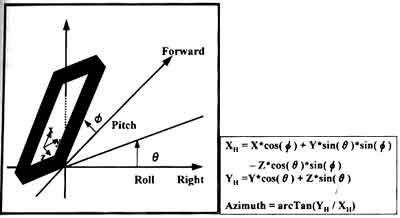
Figure 3 The way of calculating an azimuth (calculation or roll, pitch)
Also, there is following influence to the magnetic azimuth sensor when there is an object which affects the magnetic field like metal around there.
Figure 4 The influence of an object to the magnetic field.
((1) offset, (2) discrepancy of sensitivity
In order to eliminate the influence, the following method is applied.
(1). It reads the value of the X and Y coordinates while turning a magnetic sensor by 360 degrees, and draws a round plotting points around Bx and By axes. Then it determines the value of offiset as the distance from the origin.
The offset adjustment : It deducts the offset value from further measurement values Bx, By.
(2). If the round shapes a circle, it doesn't need the sensitivity adjustment. But when the round shapes an ellipse, it adjusts sensitivity using the maximum value of Bx and By.
The sensitivity adjustment : It multiplies the value of By by (Bxm + / Bym+). However, due to difficulty of drawing a round for practical use, the adjustment is done, by following subsitution means. It installs the sensor on the horizontal plane and measures at the following angle around the sensor.
The values of the offset below are subtracted from measurements
(BXm + - BXm + -)/2 (BYm + - BYm + -)/2.
The sensitivity adjustment calculates
(BXm + - (BXm + - BXm-)/2 (BYm + - (BYm + - BYm -)/2 and multiplies this value and By together. (The measurement of Bx it used as it is.)
Moreover, as this system is designed for mobile usage, the laser has rechargeable batteries, and the other devices are able to be operated with the cell.
Results
For the accuracy validation of this system, a test measurement of geodetic control points (GS14, GSI0) in GSI was applied. A reflection board was set at GSI0, and the coordinates of GSI0 as an unknown point was calculated by shooting the laser from GSI4. (In this case, only the coordinates of X,Y are calculated by the magnetic azimuth sensor and the laser, without gyro sensor.) The result is as follows.
Table 1 The difference between the acquired data and the control points data list
| The difference from the control points data list | The nominal precision | The direction of X | The direction of Y | |
| Laser | 18mm | +-3mm | 0.403m | 0.111m |
| Magnetic Sensor | 51' 31.81' | +-20 |
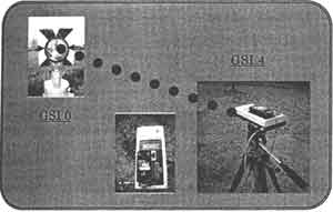
Figure 5 The data
acquisition scenery
Conclusion
After the careful
observation on the performance of each device, we confirmed the system has
enough precision.
Also, more accurate result can be expected, if an
exact constant of compass declination of the magnetic azimuth sensor (6o
50' was used) is available, and offset and sensitivity are adjusted by
other interface.
However, it is expected that the precision will be
a little worse in the actual observation, due to the error of
initialization by DGPS and so on.
Even considering such errors,
the various application of this system is
expected.
Reference
- A.Takuma, R.Shibasaki, M.Fujii (1997)
"Development of New User Interface for 3D GISusing Mobile Terminal", ACRS, 1997 (October), K-7-1~K-7-6.
- T.Tamura, T.Kitagawa,K.Tsuji,O.Uchida.Y.Shimogaki
"The GPS/INS Integration and KINEMATIC Photogrammetry for Mobile mapping System", ISPRS Commission V symposium, 1998(June),pp824-829.