| GISdevelopment.net ---> AARS ---> ACRS 1999 ---> Poster Session 3 |
Use of GIS for the Method of
Urban Safety Analysis and Environmental Design
Osamu MURAO and Fumio
YAMAZAKI
Institute of Industrial Science
University of Tokyo
4-6-1 Komaba, Meguro-ku, Tokyo, 153-8505, JAPAN
Tel: (81)-3-5452-6388, Fax: (81)-3-5452-6389
E-Mail:murao@iis.u-tokyo.ac.jp
Institute of Industrial Science
University of Tokyo
4-6-1 Komaba, Meguro-ku, Tokyo, 153-8505, JAPAN
Tel: (81)-3-5452-6388, Fax: (81)-3-5452-6389
E-Mail:murao@iis.u-tokyo.ac.jp
Keywords: Urban Safety, GIS, Image of the City,
Environmental Design, Disaster
Abstract
In Japan, where earthquakes occur frequently, it is important to carry out urban planning considering natural disasters. However, it appears that Japanese cities have not been designed with any definite visions of urban safety based on previous research concerning natural disasters in Japan, except for a few cases. It is necessary for people in Japan, which has been plagued with many earthquakes throughout history, to propose a future vision of a city from the viewpoint of urban safety. On the other hand, recent computer technology enabled the improvement of real-time monitoring systems after the 1994 Northledge Earthquake and the 1995 Kobe Earthquake. In this paper a method of analyzing and designing a city, based on the viewpoint of urban safety, is proposed. This method, named MUSE (Method of Urban Safety Analysis and Environmental Design), is based on the theory of The Image of the City by Lynch (1961), and some urban physical elements are defined as parts of an organic system. Using the MUSE with Arc/View 3D analyst, we can easily and visually simulate the city as a three-dimensional world, a task which previously required much time to express by models, on a monitor. The authors constructed vulnerability functions (Murao and Yamazaki, 1999) and proposed the Method for Building Collapse Risk Assessment (Murao and Yamazaki, 2000). Applying these methods of urban safety assessments to the MUSE should make it useful for early damage assessment systems. Moreover, by combining it with recent technology the MUSE will be realized for urban safety in the future.
1. Introduction
In Japan, where earthquakes occur frequently, it is important to carry out urban planning considering natural disasters. However, it appears that Japanese cities have not been designed with any definite visions of urban safety based on previous research concerning natural disasters in Japan, except for a few cases. It is necessary for people in Japan, which has been plagued with many earthquakes throughout history, to propose a future vision of a city from the viewpoint of urban safety. The proposed vision must also be useful for other countries in which earthquakes often occur. On the other hand, the recent computer technology enabled the improvement of real-time monitoring systems after the 1994 Northledge Earthquake and the 1995 Kobe Earthquake. Using future technology, it will become possible to easily simulate urban visions according to various situations. The authors constructed vulnerability functions for buildings based on actual damage data of the 1995 Kobe Earthquake (Murao and Yamazaki, 1999) and proposed the Method for Building Collapse Risk Assessment (Murao et al., 1999, Murao and Yamazaki, 2000). The use of future technology and the proposed method of urban safety assessment should be useful for early damage assessment systems. This paper focuses on urban physical environments, and we propose a method named MUSE (the Method of Urban Safety Analysis and Environmental Design) to analyze a city from the viewpoints of urban safety.
2. Image of a City
It might be difficult for us to recognize differences among cities with physical elements. Lynch (1960) proposed the method called “The Image of the City” to consider the differences between Boston, Jersey City and Los Angeles. In his theory, Lynch classified physical elements of cities into five types and analyzed the cities using the idea called imagability, as shown in Figure 1. These five types of elements which were “paths”, linear elements on which people can pass, such as like streets; “edges”, other linear elements which people cannot cross, like coasts; “districts”, areas that people recognize to be identical; and “nodes”, important intersections and symbolized “landmarks” in the city. The proposed method was an experimental attempt to analyze cities visually using urban physical elements.
3. Method of Urban Safety Analysis and Environmental Design
3.1 City as an organic system
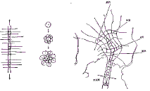
After World War II, large-scale development for new towns was carried out worldwide. In those days, some new methods for designing cities were considered by many architects to deal with the social situation. Tange (1961) in Tokyo Project 1960 and Smithon and Smithon (1967) in Urban Structuring tried to design cities in analogy to living organisms (structure of human body, trunks or leaves of trees, etc.), as shown in Figure 2. These theories or an organic city can be applied for urban safety planning. Referring to The Image of the City” by Lynch (1960) and considering the city to be an organic system, the MUSE is proposed.
Figure 1 Images of cities by Lynch (1960)
Figure 2 City as an organic system
3.2 Elements of MUSE
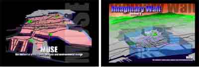
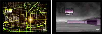
MUSE is a method of analyzing, designing and simulating a city, in which urban physical elements are defined as parts of the organic system in GIS. The physical elements are classified into the following 10 types (Figure 3, 4 and Figure 5).
Element-0: Imaginary Walls
Element-I: Subjects (as Physical Dynamic Elements): people, bicycles, cars, trains, etc.
Element-II: Shapes (as Physical Static Elements)
a. Paths (Leading Paths and Secondary Paths): streets, expressways, alleys, railways, etc.
b. Edges: coastlines, riverbanks, long walls, edges of developed districts, etc.
c. Cells: town blocks, etc.
d. Voids: open spaces, public squares, parks, playgrounds, campuses, parking lots, etc.
e. Cores: city halls, ward offices, elementary schools, hospitals, etc.
Element-III: Webs (as Systematic Elements): common ducts, lifelines, water supply, etc.
Element-IV: Nature (as Natural Elements): ponds, lakes, rivers, green belts, farms, etc.
Figure 4 Image of MUSE (1)
Figure 5 Image of MUSE (2)
Element-0: Imaginary Walls
It is important to deal with an area as a closed system. The “imaginary walls” are defined as invisible walls on the boundaries of the area. Usually the area may be an administrative district like a city. It is also possible to change the boundaries according to each occasion. The “imaginary walls” are vertical planes to close off the area. Imagining these walls in the area of analysis, it becomes possible to divide the city into inside and outside and to measure such factors as the amount of traffic, traffic density, and the number of distribution channels.
Element-I: Subjects (as Physical Dynamic Elements)
We often compare a city to a stage as described by Lewis Mumford (1895-1990). It seems that the city has been developed as an artificial stage for people, the actors, and an audience. Subjects, such as people, cars, and trains, are defined as the principal dynamic element in the MUSE. In most cases, the materials and some information are transported by the movement of the “subjects”, like blood in a body.
Element-II: Shapes (as Physical Static Elements)
In the MUSE the main objects are urban physical environments, which are represented by the “shapes” as physical static elements. By operating these elements and considering these relationships, we can analyze the city.
Element-IIa. Paths (Leading Paths and Secondary Paths)
“Paths” are linear networked elements on which the “subjects” can travel, such as streets, expressways, alleys, and railways. The “paths” are public streets for the “subjects” in most cases; it is possible to put the “nature”, such as trees, on them to make a good view, and to put “webs”, such as a common ducts, under them for urban safety. The network of “paths” is like blood vessels and make up the structure of the city. Moreover, according to the size or the purpose, the “paths” are classified into two types: “leading paths” and “secondary paths”. Connected to other areas, the “leading paths” lead human activities in the city and can make up the principal networks of lifelines. In contrast, “secondary paths” are narrow humanscale streets, such as alleys, which are familiar to the residents.
Element-IIb: Edges
“Edges” are other linear elements which people cannot cross, such as coastlines, riverbanks, long walls, and edges of developed districts. These elements are useful in preventing of the spread of fires. By making on “edge” in a dangerous zone occupied by many old wooden houses, it is possible to lessen the amount of risk of the area.
Element-IIc: Cells
“Cells” are town blocks as fundamental units of the organic city in the MUSE. There are many different buildings in each “cell” and it has different characteristics according to the structural types and construction period. By applying the vulnerability functions derived by Murao and Yamazaki (1999) or the Building Collapse Risk Assessment (Murao and Yamazaki 2000) to the “cell”, as shown in Figure 6, we can estimate the dangerous area in the city.
Element-IId: Voids
“Voids” are places not occupied by buildings, such as open spaces, public squares, parks, playgrounds, campuses, parking lots. People gather in the “voids” to take part in various urban activities: taking a walk, meeting with others, playing, evacuating from fires, etc. Networks of “voids” and “paths” influence urban safety.
Element-IIe: Cores
“Cores” are point elements, such as buildings important in the case of a disaster: city halls, ward offices, elementary schools, hospitals, electric substations, etc. These buildings have special functions for disaster management, evacuation, utilities, lifeline control, and health care.
Element-III: Webs (as Systematic Elements)
While the “shapes” are the physical elements on the ground, the “webs” are basically systematic elements underground. The “webs” include each lifeline system, such as common ducts, water pipes, and optical fiber cables, and the systems are related to the “cores”.
Element-IV: Nature (as Natural Elements)
A city has its own nature, such as lakes, rivers, forests, groves and fields, according to its geographical features or climate. These natural elements, “nature”, will be essential elements in the urban safety analysis and environmental design. Water from a river is useful for extinguishing fires, and networked greenbelts in the city can be firebreak belts. By combining “nature” with artificial elements, it is possible to make the city comfortable and safe.
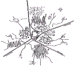
Figure 6 Display of urban safety analysis by the MUSE
4. Conclusions
In this paper a method of analyzing and designing a city was proposed, from the viewpoint of urban safety. The proposed method, called MUSE (the Method of Urban Safety Analysis and Environmental Design), is based on the theory of The Image of the City by Lynch (1961), and the urban physical elements are defined as parts of an organic system. Using the MUSE with Arc/View 3D analyst, we can easily visually simulate the city as a three-dimensional world, a task which previously required much time by making models, on a monitor. The authors constructed vulnerability functions (Murao and Yamazaki, 1999) and proposed the Method for Building Collapse Risk Assessment (Murao and Yamazaki, 2000). By applying these urban safety assessment methods to the MUSE, it should be useful for early damage assessment systems. Moreover, by combining it with recent technology, the proposed method will be realized for urban safety in the future.
References
Abstract
In Japan, where earthquakes occur frequently, it is important to carry out urban planning considering natural disasters. However, it appears that Japanese cities have not been designed with any definite visions of urban safety based on previous research concerning natural disasters in Japan, except for a few cases. It is necessary for people in Japan, which has been plagued with many earthquakes throughout history, to propose a future vision of a city from the viewpoint of urban safety. On the other hand, recent computer technology enabled the improvement of real-time monitoring systems after the 1994 Northledge Earthquake and the 1995 Kobe Earthquake. In this paper a method of analyzing and designing a city, based on the viewpoint of urban safety, is proposed. This method, named MUSE (Method of Urban Safety Analysis and Environmental Design), is based on the theory of The Image of the City by Lynch (1961), and some urban physical elements are defined as parts of an organic system. Using the MUSE with Arc/View 3D analyst, we can easily and visually simulate the city as a three-dimensional world, a task which previously required much time to express by models, on a monitor. The authors constructed vulnerability functions (Murao and Yamazaki, 1999) and proposed the Method for Building Collapse Risk Assessment (Murao and Yamazaki, 2000). Applying these methods of urban safety assessments to the MUSE should make it useful for early damage assessment systems. Moreover, by combining it with recent technology the MUSE will be realized for urban safety in the future.
1. Introduction
In Japan, where earthquakes occur frequently, it is important to carry out urban planning considering natural disasters. However, it appears that Japanese cities have not been designed with any definite visions of urban safety based on previous research concerning natural disasters in Japan, except for a few cases. It is necessary for people in Japan, which has been plagued with many earthquakes throughout history, to propose a future vision of a city from the viewpoint of urban safety. The proposed vision must also be useful for other countries in which earthquakes often occur. On the other hand, the recent computer technology enabled the improvement of real-time monitoring systems after the 1994 Northledge Earthquake and the 1995 Kobe Earthquake. Using future technology, it will become possible to easily simulate urban visions according to various situations. The authors constructed vulnerability functions for buildings based on actual damage data of the 1995 Kobe Earthquake (Murao and Yamazaki, 1999) and proposed the Method for Building Collapse Risk Assessment (Murao et al., 1999, Murao and Yamazaki, 2000). The use of future technology and the proposed method of urban safety assessment should be useful for early damage assessment systems. This paper focuses on urban physical environments, and we propose a method named MUSE (the Method of Urban Safety Analysis and Environmental Design) to analyze a city from the viewpoints of urban safety.
2. Image of a City
It might be difficult for us to recognize differences among cities with physical elements. Lynch (1960) proposed the method called “The Image of the City” to consider the differences between Boston, Jersey City and Los Angeles. In his theory, Lynch classified physical elements of cities into five types and analyzed the cities using the idea called imagability, as shown in Figure 1. These five types of elements which were “paths”, linear elements on which people can pass, such as like streets; “edges”, other linear elements which people cannot cross, like coasts; “districts”, areas that people recognize to be identical; and “nodes”, important intersections and symbolized “landmarks” in the city. The proposed method was an experimental attempt to analyze cities visually using urban physical elements.
3. Method of Urban Safety Analysis and Environmental Design
3.1 City as an organic system
After World War II, large-scale development for new towns was carried out worldwide. In those days, some new methods for designing cities were considered by many architects to deal with the social situation. Tange (1961) in Tokyo Project 1960 and Smithon and Smithon (1967) in Urban Structuring tried to design cities in analogy to living organisms (structure of human body, trunks or leaves of trees, etc.), as shown in Figure 2. These theories or an organic city can be applied for urban safety planning. Referring to The Image of the City” by Lynch (1960) and considering the city to be an organic system, the MUSE is proposed.
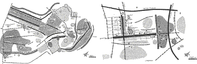 | |
| (a) Boston | (b) Los Angeles |
Figure 1 Images of cities by Lynch (1960)
 |
 | |
| Opened System and Closed System | Axis of Possibility for Urban Development | |
| (a) Tokyo 1960 by Tange (1961) | (b) Cluster City by Smithon and Smithon (1967) | |
Figure 2 City as an organic system
3.2 Elements of MUSE
MUSE is a method of analyzing, designing and simulating a city, in which urban physical elements are defined as parts of the organic system in GIS. The physical elements are classified into the following 10 types (Figure 3, 4 and Figure 5).
Element-0: Imaginary Walls
Element-I: Subjects (as Physical Dynamic Elements): people, bicycles, cars, trains, etc.
Element-II: Shapes (as Physical Static Elements)
a. Paths (Leading Paths and Secondary Paths): streets, expressways, alleys, railways, etc.
b. Edges: coastlines, riverbanks, long walls, edges of developed districts, etc.
c. Cells: town blocks, etc.
d. Voids: open spaces, public squares, parks, playgrounds, campuses, parking lots, etc.
e. Cores: city halls, ward offices, elementary schools, hospitals, etc.
Element-III: Webs (as Systematic Elements): common ducts, lifelines, water supply, etc.
Element-IV: Nature (as Natural Elements): ponds, lakes, rivers, green belts, farms, etc.
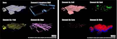 | |
| (a) Total Image of
MUSE | (b) Element 0: Imaginary
Wall |
 | |
| (c) Element II-a: Path | (d) Element II-b: Edge |
Figure 4 Image of MUSE (1)
 | |
| (e) Element II-c:
Cell | (f) Element II-d:
Void |
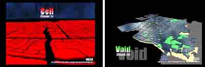 | |
| (g) Element II-e: Core | (h) Element III: Web |
Figure 5 Image of MUSE (2)
Element-0: Imaginary Walls
It is important to deal with an area as a closed system. The “imaginary walls” are defined as invisible walls on the boundaries of the area. Usually the area may be an administrative district like a city. It is also possible to change the boundaries according to each occasion. The “imaginary walls” are vertical planes to close off the area. Imagining these walls in the area of analysis, it becomes possible to divide the city into inside and outside and to measure such factors as the amount of traffic, traffic density, and the number of distribution channels.
Element-I: Subjects (as Physical Dynamic Elements)
We often compare a city to a stage as described by Lewis Mumford (1895-1990). It seems that the city has been developed as an artificial stage for people, the actors, and an audience. Subjects, such as people, cars, and trains, are defined as the principal dynamic element in the MUSE. In most cases, the materials and some information are transported by the movement of the “subjects”, like blood in a body.
Element-II: Shapes (as Physical Static Elements)
In the MUSE the main objects are urban physical environments, which are represented by the “shapes” as physical static elements. By operating these elements and considering these relationships, we can analyze the city.
Element-IIa. Paths (Leading Paths and Secondary Paths)
“Paths” are linear networked elements on which the “subjects” can travel, such as streets, expressways, alleys, and railways. The “paths” are public streets for the “subjects” in most cases; it is possible to put the “nature”, such as trees, on them to make a good view, and to put “webs”, such as a common ducts, under them for urban safety. The network of “paths” is like blood vessels and make up the structure of the city. Moreover, according to the size or the purpose, the “paths” are classified into two types: “leading paths” and “secondary paths”. Connected to other areas, the “leading paths” lead human activities in the city and can make up the principal networks of lifelines. In contrast, “secondary paths” are narrow humanscale streets, such as alleys, which are familiar to the residents.
Element-IIb: Edges
“Edges” are other linear elements which people cannot cross, such as coastlines, riverbanks, long walls, and edges of developed districts. These elements are useful in preventing of the spread of fires. By making on “edge” in a dangerous zone occupied by many old wooden houses, it is possible to lessen the amount of risk of the area.
Element-IIc: Cells
“Cells” are town blocks as fundamental units of the organic city in the MUSE. There are many different buildings in each “cell” and it has different characteristics according to the structural types and construction period. By applying the vulnerability functions derived by Murao and Yamazaki (1999) or the Building Collapse Risk Assessment (Murao and Yamazaki 2000) to the “cell”, as shown in Figure 6, we can estimate the dangerous area in the city.
Element-IId: Voids
“Voids” are places not occupied by buildings, such as open spaces, public squares, parks, playgrounds, campuses, parking lots. People gather in the “voids” to take part in various urban activities: taking a walk, meeting with others, playing, evacuating from fires, etc. Networks of “voids” and “paths” influence urban safety.
Element-IIe: Cores
“Cores” are point elements, such as buildings important in the case of a disaster: city halls, ward offices, elementary schools, hospitals, electric substations, etc. These buildings have special functions for disaster management, evacuation, utilities, lifeline control, and health care.
Element-III: Webs (as Systematic Elements)
While the “shapes” are the physical elements on the ground, the “webs” are basically systematic elements underground. The “webs” include each lifeline system, such as common ducts, water pipes, and optical fiber cables, and the systems are related to the “cores”.
Element-IV: Nature (as Natural Elements)
A city has its own nature, such as lakes, rivers, forests, groves and fields, according to its geographical features or climate. These natural elements, “nature”, will be essential elements in the urban safety analysis and environmental design. Water from a river is useful for extinguishing fires, and networked greenbelts in the city can be firebreak belts. By combining “nature” with artificial elements, it is possible to make the city comfortable and safe.
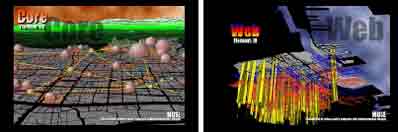 | |
| (a) Distribution of Strong Ground Motion | (b) Building Collapse Risk |
Figure 6 Display of urban safety analysis by the MUSE
4. Conclusions
In this paper a method of analyzing and designing a city was proposed, from the viewpoint of urban safety. The proposed method, called MUSE (the Method of Urban Safety Analysis and Environmental Design), is based on the theory of The Image of the City by Lynch (1961), and the urban physical elements are defined as parts of an organic system. Using the MUSE with Arc/View 3D analyst, we can easily visually simulate the city as a three-dimensional world, a task which previously required much time by making models, on a monitor. The authors constructed vulnerability functions (Murao and Yamazaki, 1999) and proposed the Method for Building Collapse Risk Assessment (Murao and Yamazaki, 2000). By applying these urban safety assessment methods to the MUSE, it should be useful for early damage assessment systems. Moreover, by combining it with recent technology, the proposed method will be realized for urban safety in the future.
References
- Lynch, Kevin, (1960). The Image of the City, MIT Press.
- Murao, O., Tanaka, H., and Yamazaki, F., (1999). “Comparison of Building Collapse Risk and Actual Building Damage Due to the 1995 Kobe Earthquake,” Proceedings of 6th Japan/United States Workshop on Urban Earthquake Hazard Reduction, Kobe, Japan.
- Murao, O., and Yamazaki, F., (1999). “Development of Fragility Curves for Buildings Based on Damage Data due to the Hyogoken-Nanbu Earthquake,” Proceedings of the Asian-Pacific Symposium on Structural Reliability and Its Applications, 259-269, Taipei, Taiwan.
- Murao, O., and Yamazaki, F., (2000). “New Method for Building Collapse Risk Assessment Based on Damage Data Due to the 1995 Kobe Earthquake,” Proceedings of the 12th World Conference on Earthquake Engineering (in printing).
- Smithon, P., and Smithon, A., (1967). Urban Structuring, Studio Vista Ltd.
- Tange, K., (1961). Tokyo Project 1960, Kenzo Tange Laboratory.