| GISdevelopment.net ---> AARS ---> ACRS 1999 ---> Poster Session 1 |
Application of remote sensing
for extraction of road Information
Manzul Kumar
Hazarika, Kiyoshi Honda,
Lal Samarakoon, and Shunji Murai
Asian Center for Research on Remote Sensing (ACRoRS)
STAR Program, Asian Institute of Technology,
Km. 42, Paholyothin Highway, Klong Luang, Pathumthani 12120, Thailand.
Tel : +66-2-524-6148 Fax : +66-2-524-6147
E-mail : manzul@ait.ac.th
Keywords: Remote Sensing, information
extraction. Asian Center for Research on Remote Sensing (ACRoRS)
STAR Program, Asian Institute of Technology,
Km. 42, Paholyothin Highway, Klong Luang, Pathumthani 12120, Thailand.
Tel : +66-2-524-6148 Fax : +66-2-524-6147
E-mail : manzul@ait.ac.th
Abstract
Road network of the Asia plays a vital role in economic development of the region by providing access to underdeveloped areas. Keeping the importance of an efficient road network in view, Asian Highway project has been initiated by the United Nations Economic and Social Commission for Asia and the Pacific (UN-ESCAP) to promote and co-ordinate the development of international road transport in the Asian region and stimulate economic growth. The major part of Asian Highway is the existing roads and a considerable portion of these roads needs to be upgraded to meet the Asian highway standard. A database on these roads is required and remote sensing satellites with their synoptic view and repetitive coverage offer a possibility for obtaining such information.
Capabilities of remote sensing data in road identification and their width estimation have been examined by setting up several test-sites in Thailand. Widths of the roads at the test sites are 5m, 15m, 35m and 64m. SPIN-2 (2m) data, used in this study, has the best spatial resolution; followed by ADEOS Panchromatic (8m), SPOT Panchromatic (10m), ADEOS Multispectral (16m) and LANDSAT TM (30m).
All the sensors can identify 35m and 64m wide road. ADEOS Multispectral and LANDSAT TM data cannot identify a road having a width of 15m or less. A 5m wide can be identified by SPIN-2 data only. Spatial resolution of data contributes more to the clarity of a road than the multi-band observation capability. However, the surrounding environment along the road also affects on its clarity. If the background of a road has a very different reflectance characteristic from the road itself, for example, when a road passes through a paddy field, possessing homogeneous vegetative cover, then it becomes very distinct. On the other hand, if a road passes through an urban area, which has similar reflectance, it is difficult to identify.
Two methods have been tested for road width estimation. One is to measure the road width on printed images and the another is to count the number of pixels on a computer display. Result shows that in most of the cases, remote sensing data has the capability to estimate the width with an accuracy of half of the spatial resolution or at least the accuracy better than its resolution.
Road materials like asphalt and concrete can not be discriminated using the data from any of the five sensors, even though asphalt and concrete have different reflectance characteristics. In ideal condition, it may be possible to distinguish one from other. But on a road, due to wearing of rubber particles from the vehicles, which stick to the road surface, both the concrete and asphalt surface gives similar reflectance characteristics, after a road become operational.
Introduction
Major portion of the route identified by the UN-ESCAP is existing roads which needs upgrading to Asian Highway specifications. Accordingly, information of these routes are required for making a plan. Many of the Asian countries are very poor and some of them are suffering from economic and political instability. In such a situation, only a few countries possess updated information for existing roads. Further, updating road information through physical survey is not only an expensive task but also time consuming. Remote sensing technology can be effectively used to overcome such problems.
Study Area and Data Used
The area in this study falls in the northern part of the Bangkok City. Study area is extended from 100°15" to 100°45" in the East and 14°00" to 14°30" in the North. In this study, satellite data of various spatial resolutions with different sensors have been used. Data used in this study are shown in Table 1.
Table 1 Satellite data used in the
| Satellite/Sensor | Spatial Resolution | Path/Row | Acquisition Date |
| SPIN 2/KVR-1000 (Analog) | 2m | - | 1995 |
| ADEOS/AVNIR (Panchromatic) | 8m | 113/333 | 28-05-97 |
| ADEOS/AVNIR (Multispectral) | 16m | 113/333 | 25-01-97 |
| SPOT/HRV (Panchromatic) | 10m | 262/322 | 28-06-96 |
| LANDSAT/TM (Multispectral) | 30m | 129/50 | 21-05-95 |
Methodology
Data Processing
Satellite data are corrected geometrically, using Ground Control Points (GCP) taken form topographic maps (Scale 1:50,000). A first order polynomial transformation equation has been used to rectify the data set.
Identification of Road Characteristics in Different Backgrounds
Road sections with various backgrounds have been considered in study. False Colour Composite of the multispectral data and intensity image panchromatic data are used for investigating the road characteristics.
Estimation of Road Width
Road width is estimated using analog and digital methods. In analog method, each of the geometrically corrected images from different sensors is printed in a hardcopy and widths of roads are estimated from the actual measurements made on the hardcopies. SPIN-2 is printed at a scale 1:8,000 whereas ADEOS Panchromatic, SPOT Panchromatic, ADEOS Multispectral and LANDSAT TM data are printed at a scale of 1:20,000. These scales are found to be most appropriate, because pixels of the roads are not shown individually in the hard copy. A road can be measured up to an accuracy of 0.25 mm on a hardcopy image, using a ruler. Field survey was conducted to find out the actual width of the road sections for verification of results. The measured width includes both the pavements and shoulders of the road and median strip, in case of roads having more than one lane.
In digital method, numbers of pixels are counted in the perpendicular direction of a road and width of the road is estimated by multiplying pixel numbers with the pixel size. However, there are certain difficulties in counting numbers of pixels perpendicular to a road. Mixed pixels exist on the edge of a road and, in such cases, it is not an easy task to find out an accurate width of the road. This is more critical in low-resolution data.
Results and Discussions
Road Passing Through a Water Body
Clarity of a road depends on its background. Figure 1 shows a road (35m in width), passing through a water body, contaminated with molasses, in different sensors. In ADEOS AVNIR Panchromatic data, the background is very bright in the portion of the tank where water is dried out and, however, road can be seen distinctly. On the other hand, the portion of the tank, where contaminated water is available, appeared very dark and the road can also be seen clearly. In this case, molasses absorbs most of the energy whereas reflectance from the road is very high and thereby provides a very good contrast. In SPOT Panchromatic data, rainy season was just started and probably, therefore, dried out portion of the tank is not as bright as in the case of ADEOS data. This could not be confirmed due to unavailability of ground truth data at that instant of time. In ADEOS Multispectral data, the tank was full of water, therefore, the road appeared very bright against its background of dark contaminated water. LANDSAT TM data shows similar behaviour with ADEOS AVNIR Panchromatic data as both the images were acquired nearly in the same time of two different years. SPIN-2 data is not available for this area.
| ADEOS Panchromatic | SPOT Panchromatic |
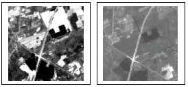 | |
| ADEOS Multispectral | LANDSAT TM |
 | |
Road Passing Through a Paddy Field
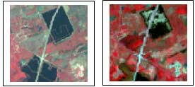
A road passing through an area with uniformly distributed vegetation, like paddy field becomes prominent due to their different reflection characteristics. A section of road with a width of 35m (Figure 2), passing through a paddy field can be seen very distinctly in ADEOS Panchromatic data. There is a very good background contrast throughout the road section and edges of the road can be identified clearly. SPOT Panchromatic data also provide a clear picture of the road. Due to the low resolution, in the case of ADEOS Multispectral data and LANDSAT TM data, edges of the road section is not prominent, though the road can be clearly identified as shown in the figure. SPIN-2 data is not available for this area.
| ADEOS Panchromatic | SPOT Panchromatic |
 | |
| ADEOS Multispectral | LANDSAT TM |
 | |
Road Passing Through an Urban Area
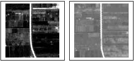
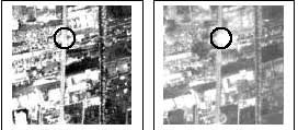
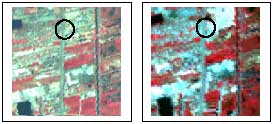
Images in Figure 3 show a section of road through an urban area. Ground width of this road section is 64m. Irrespective of spatial resolution, the section of road marked by a circle can not be identified clearly in any of the images. However, in certain sections, where background is not structural material, the road can be identified. Thus, if a road passes through such an urban area which gives similar spectral signature as construction materials, it is very difficult to identify the road. In such cases, there is a need to look for certain sections of the road with a background other than man made materials, for identification.
| ADEOS Panchromatic | SPOT Panchromatic |
 | |
| ADEOS Multispectral | LANDSAT TM |
 | |
Locating Bridges on a Road
A bridge with two parallel roads of 10m width each, one for up coming and another for down going vehicles, with a gap of 5m in between (25m in total) can be identified separately in ADEOS Panchromatic and SPOT Panchromatic data. ADEOS Multispectral and in LANDSAT TM data can not distinguish these two parallel roads separately. SPIN-2 data is not available for the location of the bridge.
Estimation Of Road Width
Estimating Width of Roads Using Analog Method
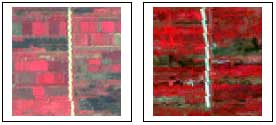
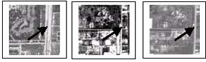
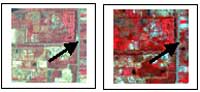
Estimated width of various road sections using different sensors are shown in Table 2. Using SPIN 2 data, a 64m wide road (Figure 4) is measured and it varies from 64m to 66m (8.00mm to 8.25 mm), giving a maximum error of 2m. The same section of road varies from 60m to 70m (3.00mm to 3.50mm) in ADEOS Panchromatic and SPOT Panchromatic data. In both of the cases, maximum error found to be 6m. Due to low resolution, edges of the same road section are not very prominent in ADEOS Multispectral data and LANDSAT TM data. In ADEOS Multispectral data width of the road varies from 60m to 75m (3.00mm to 3.75mm), giving a maximum error of 11m. In LANDSAT TM data, width of the road section varies from 50m to 70m (2.50mm to 3.50mm) with a maximum error of 14m.
| SPIN 2 | ADEOS Panchromatic | SPOT Panchromatic |
 | ||
| ADEOS Multispectral | LANDSAT TM | |
 |
||
Roads having a width of 35m can be measured, using data from all the five sensors. In SPIN-2 data, width varies from 34m to 36m (4.25mm to 4.50mm) with a maximum error of 1m. ADEOS Panchromatic data and SPOT Panchromatic data can estimate the width of the same road section in between 30m to 40m (1.50mm to 2.00mm) with a maximum error of 5m. In ADEOS Multispectral data, width of the road varies from 30m to 45m (1.50mm to 2.25mm) and maximum error in this case is 10m. In LANDSAT TM data, the width of the road section varies from 25m to 45m (1.25mm to 2.25mm) with a maximum error of 10m.
Width of a 15m wide road varies from 14m to 16m (1.75mm to 2.00mm) in SPIN-2 data, giving a maximum error of 1m. Width of the same section of road varies from 15m to 20m (0.75mm to 1.00mm) in ADEOS Panchromatic and SPOT Panchromatic data with a maximum error is 5m in both the cases. Such a road (15m in width) can not be identified in ADEOS Multispectral or LANDSAT TM data.
In SPIN 2 data, a 5m wide road varies from 4m to 6m giving a maximum error of 1m.
Table 2 Estimating width of road a using analog method
| 1 | 2 | 3 | 4 | 5 | 6 | 7 | 8 |
| Actual width | Satellite sensors | Range of road width in image milli meter | Range of estimated width meter | Mean meter | Error (5-1) meter | Range of error (4-1) meter | Maximum error meter |
| 64m | SPIN-2 | 8.00-8.25 | 64-66 | 65 | 1 | 0 ~ +2 | 2 |
| ADEOS Pan * | 3.00-3.50 | 60-70 | 65 | 1 | -4 ~ +6 | 6 | |
| SPOT Pan | 3.00-3.50 | 60-70 | 65 | 1 | -4 ~ +6 | 6 | |
| ADEOS Mul ** | 3.00-3.75 | 60-75 | 67.5 | 3.5 | -4 ~ 11 | 11 | |
| LANDSAT TM | 2.50-3.50 | 50-70 | 60 | -4 | -14 ~+6 | 14 | |
| 35m | SPIN-2 | 4.25-4.50 | 34-36 | 35 | 0 | -1~ +1 | 1 |
| ADEOS Pan | 1.50-2.00 | 30-40 | 35 | 0 | -5 ~ +5 | 5 | |
| SPOT Pan | 1.50-2.00 | 30-40 | 35 | 0 | -5 ~ +5 | 5 | |
| ADEOS Mul | 1.50-2.25 | 30-45 | 37.5 | 2.5 | -5 ~ +10 | 10 | |
| LANDSAT TM | 1.25-2.25 | 25-45 | 35 | 0 | -10 ~ +10 | 10 | |
| 15m | SPIN-2 | 1.75-2.00 | 14-16 | 15 | 0 | -1~ +1 | 1 |
| ADEOS Pan | 0.75-1.00 | 15-20 | 17.5 | 2.5 | -0~ +5 | 5 | |
| SPOT Pan | 0.75-1.00 | 15-20 | 17.5 | 2.5 | -0~ +5 | 5 | |
| ADEOS Mul | - | - | - | - | - | - | |
| LANDSAT TM | - | - | - | - | - | - | |
| 5m | SPIN-2 | 0.50-0.75 | 4-6 | 5 | 0 | -1~ +1 | 1 |
| ADEOS Pan | - | - | - | - | - | - | |
| SPOT Pan | - | - | - | - | - | - | |
| ADEOS Mul | - | - | - | - | - | - | |
| LANDSAT TM | - | - | - | - | - | - |
Table 3 Estimating width of a road using digital method
| 1 | 2 | 3 | 4 | 5 | 6 | 7 | 8 | 9 |
| Actual width | Satellite sensors | No.of pixels | Pixel size meter | Range of estimated width meter | Mean meter | Error(6-1) meter | Range of error(5-1) meter | Maxi- mum error meter |
| 64m | SPIN-2 | 31-32 | 2 | 62-64 | 63 | -1 | -2 ~ 0 | 2 |
| ADEOS Pan * | 7-8 | 8 | 56-64 | 60 | -4 | -8 ~ 0 | 8 | |
| SPOT Pan | 6-7 | 10 | 60-70 | 65 | 1 | -4 ~ +6 | 6 | |
| ADEOS Mul ** | 3-4 | 16 | 48-64 | 56 | -8 | -16 ~ +0 | 16 | |
| LANDSAT TM | 2-3 | 30 | 60-90 | 75 | 11 | -4 ~ +26 | 26 | |
| 35m | SPIN-2 | 17-18 | 2 | 34-36 | 35 | 0 | -1 ~ +1 | 1 |
| ADEOS Pan | 4-5 | 8 | 32-40 | 36 | 1 | -3 ~ +5 | 5 | |
| SPOT Pan | 3-4 | 10 | 30-40 | 35 | 0 | -5 ~ +5 | 5 | |
| ADEOS Mul | 2-3 | 16 | 32-48 | 40 | 5 | -3 ~ +13 | 13 | |
| LANDSAT TM | 1-2 | 30 | 30-60 | 45 | 10 | -5 ~ +25 | 25 | |
| 15m | SPIN-2 | 7-8 | 2 | 14-16 | 15 | 0 | -1 ~ +1 | 1 |
| ADEOS Pan | 1-2 | 8 | 8-16 | 12 | -3 | -7 ~ +1 | 7 | |
| SPOT Pan | 1-2 | 10 | 10-20 | 15 | 0 | -5 ~ +5 | 5 | |
| ADEOS Mul | - | 16 | - | - | - | - | - | |
| LANDSAT TM | - | 30 | - | - | - | - | - | |
| 5m | SPIN-2 | 2-3 | 2 | 4-6 | 5 | 0 | -1 ~ +1 | 1 |
| ADEOS Pan | - | 8 | - | - | - | - | - | |
| SPOT Pan | - | 10 | - | - | - | - | - | |
| ADEOS Mul | - | 16 | - | - | - | - | - | |
| LANDSAT TM | - | 30 | - | - | - | - | - |
Estimating Width of Roads Using Digital Method
Estimated width of the same road sections (as analog method above) using digital method is summarised in Table 3. Estimated width of a 64m wide road (Figure 4) varies from 62m to 64m in this method, giving a maximum error of 2m. In ADEOS Panchromatic data width varies from 56m to 64m, giving a maximum error of 8m whereas in SPOT Panchromatic data, the estimated width varies from 60m to 70m with a maximum error of 6m. ADEOS Multispectral and LANDSAT TM data can estimate such a road with a maximum error of 16m and 26m respectively.
A 35m wide road varies from 34m to 36m in SPIN-2 data, giving a maximum error of 1m. Width of the same road of section road varies from 32m to 40m and 30m to 40m in ADEOS Panchromatic data and SPOT Panchromatic data respectively with a maximum error of 5m in each case. ADEOS Multispectral and LANDSAT TM data give a maximum error of 13m and 25m respectively while estimating the width.
SPIN-2 data measures a 15m wide road with a maximum error of 1m. ADEOS Panchromatic and SPOT Panchromatic data can measure the width of the road with a maximum error of 7m and 5m respectively whereas ADEOS Multispectral and LANDSAT TM data can not recognise such a road.
A 5m wide road can be measured with a maximum error of 1m using SPIN-2 data.
Discrimination of Asphalt and Concrete Road
Concrete and asphalt have different reflectance characteristics. In ideal condition, it is possible to distinguish one from another using remote sensing data. But, if these materials are used in roads, due to wearing of vehicle tyres, black coloured rubber particles begin to stick on their surface after the road become operational. As a result, concrete road surface gives similar kind of reflectance as asphalt.
Conclusion
Identification of road characteristics depends on its surrounding land cover or background and spatial resolution of the data. If a road passes through an area having very different spectral signature from its own, such as uniform vegetation like a paddy field, its edges can be identified clearly. In a background like a water body, edges of a road are also prominent. Roads are not well identified, if it pass through an urban area with plenty of structural materials. ADEOS Panchromatic and SPOT Panchromatic data provide more information on a bridge than ADEOS Multispectral or LANDSAT TM.
Due to high cost, limited coverage and huge computational resource requirement, SPIN-2 data may not be suitable for using in Asian Highway of 90,000km in length, even though it identifies a road distinctly and estimates its width with a maximum error of 2m in all four types of roads considered in this study. ADEOS Panchromatic data and SPOT Panchromatic data can identify the roads having width of 64m, 35m and 15m distinctly. Among these three kinds of roads, maximum error in width measurement is found in the case of 64m wide road, using ADEOS Panchromatic and SPOT Panchromatic data and it is 6m and 8m in analog and digital methods respectively. Data of such a resolution is comparatively cheap and covers a large area repetitively, therefore, it will be very useful for Asian Highway. ADEOS Multispectral data and LANDSAT TM data has capability to identify a road up to a minimum width of 35m, but can not estimate the width of a road closely to its actual width. Extracted road information from satellite data will be also useful for cross checking the accuracy of the highway database available with some of Asian Highway member countries of the UN-ESCAP.
References
- United Nations, 1998. Asian Highway, Joint ESCAP-Japan Symposium on Highway Development, ST/ESCAP/1829, Sales No. E.98.II.F.72, New York.