| GISdevelopment.net ---> AARS ---> ACRS 1999 ---> Oceanography/Coastal Zone |
University Putra Malaysia,
Tel: 603-9486101-2067 Fax: 603-9488939
E-mail: shahrzadcom@hotmail.com
Abstract
Operational remote sensing and Geographic Information System (GIS) are important tools for oil spill research and development activities. To facilitate these requirements, GIS based oil spill contingency plan was developed for Strait of Malacca (SOM) composed, ESI map which created and served as quick references for oil and chemical spill responders. Remotely sensed data are used for detecting the oil spill to support the contingency plan at a specific location and trajectory model are applied to predict spill movement. Finally, the plan preceded to assesss resouce requirement and response priorities to manage oil spill in SOM.
Introduction
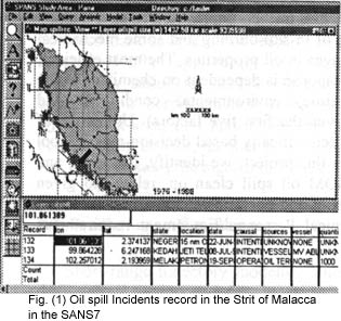
Shipping casualities often resulted in serious accidental spills as experienced in the Straits of Malacca (SOM) in the past decade. Major spills in the SOM were either due to collision of tankers such as that of Diego Sillang (1978-5500 tons) and recently VI.CC (1997-120,000 tons), groundings such as that of Showamaru (1975-4000 tons) or due to fire and bad weather, such as Tolasea (1975-60 tons) and M.V. Asian in 1997 (fig. 1). Most of the shipping casualities occurred in Singapore and a few near the one fathom bank in the SOM in the West Coast of Peninsular Malaysia. Considering the record of oil spill from 1975 till 1977 (fig.1) it is evident that major environmental issues in SOM is water pollution and oil spill. Operational remote sensing and (GIS) are important tools for oil spill research and development activities. Tan (1983) developed an oil spill preparedness plan, based on wind and sea surface currents in the East Coast of Malaysia including Sabah and Sarawak coastal water. Cheong H. et al. (1992) developed the numerical modeling of tidal motion in the southern waters of Singapore and south of the Malacca Strait. Also Pohlmann T. (1978) has carried out a three-dimensional circulation model for the South China sea and the Strait of Malacca. Such efforts are published by Regional Program for the prevention and Management of marine Pollution in the East Asian Seas (GEF/UNDP/IMO), for example: Malacca Straits, Documentaion Project (1995) Malacca Straits, Environmental Profile (1997) and Malacca Straits, Initial Risk Assessment (1977).
Methodology
Environmental Impact Assessment
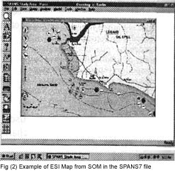
A main objective of environmental impact in this study, after protecting human life, is to reduce the environmental consequences of both spills and cleanup efforts. To do this, it is necessary to identify vulnerable coastal locations before a spill happens, so that protection priorities can be established and cleanup strategies identified. To meet this requirement, Environmental Sensitivity Index (ESI) map has been produced for the study area (fig. 2). These maps seve as quick references for oil and chemical spill responders and coastal zone managers. ESI maps contain three kinds of information: 1) Shorelines are color-coded to indicate their sensitivity to oiling. 2) Sensitive biological resoues, such as seabird colonies and marine mammal hauling grounds, are depicted by special symbols on the maps. 3) ESI maps also show important human-use resources, such as water intakes, marinas, and swimming beaches.. Table 1 represents the ESI shoreline sensitivity rankings, applied to three different aquatic settings. In this table, "ESI No." is the number of each shoreline ranking. Descriptions of the types of shorelines that typify each ranking in estuarine, lacustine, and riverine environments are shown in the remaining three columns of the table.
Oil Spill Detection
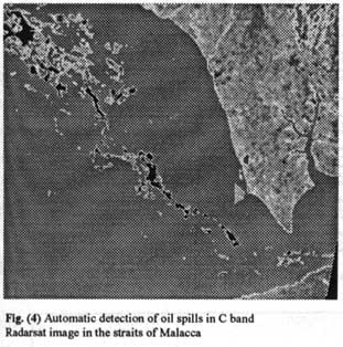
Remote sensing are applied to identify oil spill as a main part of contingency planning in the strait of Malacca. The project consistsof four steps: 1) filtering of the images to reduce speckle noise. Gamman function in PCI's EASI/PACE image processing system is performs spatial filtering on each individual pixel in an image using the grey-level values in a square window surrondng each pixel. To remote isolated pixel (pixel of very high or very ow value) in homogeneous area all pixels are filtered. In order to filter pixels located near the edges of the image, edge-pixel values are replicated to give sufficient data. 2 ) dark slicks detection involving the location on the images of all dark patches wich might possibly be oil slick, 3) feature extraction in which a set of backscatter textural and geometric features are extracted for each dark slicks, and 4) dark slick classification in which oil slicks are distinguished form other phenomena that dampen out short waves creating dark slicks are classified into possible oil slicks and look-alikes based on the extracted features (Fig. 3,4). For each dark spot, a set of features in computed. The features constitute general, standard descriptors often applied for regions in general image analysis, and additional features particularly suited for oil slick detection. The features are: Slick complexity, local area contrast ratio, bordr gradient, smootheness contrast locally, distance to a bright object, slick width, slick area, first planar moment, power-to-mean (PMR) ratio of the slick, nuber of neighbouring objects, number of objects in the scene, and homogeneity of the surroundings. Fig (3) represents the algorithm for identifications of oil spill in the Strait of Malacca.
 |
 |
Predicting spill movement
Short-range trajectory modeling
studies are the most important, therefore it should be done on real time
to give day-to-day support oil spill contingency paln at a specific spill.
In this project, oil spill trajectory simulations are assumed.
Hypothetical spill trajectories will be simulated for each of the
potential lauch areas across the entrance SOM. These simulations assumed
more than hundred spills occurring in each of the four seasons of the year
from each launch area. Combining both the current and wind effects, the
relationship of t he movement of the centre of mass of the slick to these
factors can be expressed as.![]() (1)
(1)
Regardless the physical properties of oil and water, the size
of the spill and its spreadings tendency, the resultant vector may be
estimated as:
V = ![]() (2)
(2)
Were V is spill drift
velocity; Uw, wind speed at 10m above the surface; Uc, current speed near
the surface; Kw, unit vector in the direction of wind drift (inclined at
250 cum sole to the wind direction); and Kc, unit vector in the direction
of current Pgkurup (1983). In order to model the current velocity by radar
data in the study area Martin, equation (3) was applied.
Ux =
-Dxdxv2 / DflR
(3)
Where x is the displacement vector dx is the pixel spacing in
azimuth direction and Df is the difference between the look centre
frequencies of two successive images and l is the wavelength and R is the
distance between antenna and the target and v is satellite velocity.
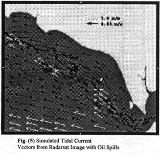
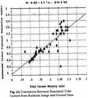
Figure (5) shows the simulated current velocity from Radarsat image. The
drift currents are towards the north direction. Figure (6) shows a good
correlation between simulated tidal current from Radarsat image and ground
data. The maximum current speed detected in the study area is about 1.4
m/sec.
 |
 |
Assessment of Resource Requirement
Planning and
decision-making in oil spill response requires and understanding of oil
weathering processes and subsequent changes in an oils characteristics and
the effect of these changes on response technologies over time. These
changes have an important influence on the usefulness and effectiveness of
response methods and technologies. Three major categories of response
(clean-up)methods are available: (1) mechanical recovery, (2) chemical
treatment, and (3) in-situe buring. Methods and technologies in each of
these categories are limited by environmental conditions both
operationally and as a result of the changes in oil characteristics over
time. Integration of a technology database, using changes in specific oil
characteristics as a time reference has further improved decision-making
capabilities. In additoon to dispersants, effective use of
in-siute-burings and some mechanical technologies in limited in time and
government by changes in oil properties. The most efficient,
environmentally preferred, and cost effective spill response is dependent
on chemistry of the spilled product, quantity, location, response time,
environmental conditions, and effectiveness of available response
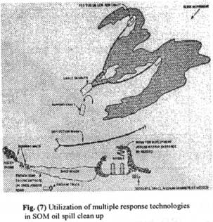
technologies (give the first five factors). Utilization of multiple
response technologies requires a rapid and scientifically based
decision-making tool and and integrated system of response capabilities.
In this project, we identify, delineate, and estimate selected response
technologies used in SOM oil spill clean up, related to given
environmental conditions, changes in oil characteristics and operational
considerations in the Straits of Malacca (Fig 7). Table (2) provides typical Personnel/Equipment
requirements from Naval Spill Response
experience.
Conclusion
Modeling, analysis and various
functions of digital image processing were applied to develop an oil spill
contingency plan for the Strait of Malacca. In this study remote sensing
and GIS tools play a valuable part in protecting the sensitive
environmental and socioeconomic resources and acting as an effective
repository for local and regional knowledge of those resources in the
strait of Malacca.
Reference
- Anon (eds.), 1999. Environmental Law Reporter, Environmental Low
Institute Washington, D. C. Oil Pollution Deskbook.
- Anon (eds.). 1995. Malacca Straits Documentation Project. Tropical
Coasts; 2(1).
- Anon, 1999. Malacca strait Environmental Profile, Regional Program
for the prevention and management of Marine Pollution in the east Asian
Seas (GEF/UNDP/IMO). Printed in Manila, Philippines.
- Cheong H - F, Shankar, N. J., Chan C - T., 1992 Numerical modeling
of tidal motion in the southern waters of Singapore; Depatment of Civil
Engineering, National University of Singapore, 10 Kent Ridge Crescent,
0511 Singapore,.
- Ging Tuang Tan (Sarawak Shell Berhad Sabah Shell petroleum company
Lutong, Sarawak Malaysis)., 1983. Oil spill preparedness in a tropical
offshore area. Oil spill conference San Antonio, Texas. February 28-
March 3,
- Martain K., 1997. Detection and Focuses Imaging of Moving Objects
Evaluating a sequence of Single Look SAR images. 3rd international
Airborne Remote Sensing Conference and Exhibition, Copenhage, Denmark,
Vol. I, pp.393-400.
- Peter Calow and Valery E. Forbes, 1997. Malacca strait: Initial Risk
Assessment, Regional Program for the Prevention and management of Marine
Pollution in the East Asian Seas (GEF/UNDP/IMO). Printed in Manila,
Philippines.z
- Pgkurup., 1983. Ol slick drift trajectory for hypothetical spills in
the Arabin Sea; India Jornal of Marine Scinces, 12, 1-10.
- Pohlmann T. A., 1987 three dimensional circulation model of the
south China Sea; Institute fur meereskunde der universitat Hamburg
Heimhuder Strafe 71,2000 Hamburg 13, FRG.,
| ESI No. | ESTUARINE | LACUSTRINE | RIVERINE |
| 1A | Exposed rocky shores | Exposed rocky shores | Exposed rocky banks |
| IB | Exposed, Soild man-made structures | Exposed, soild man-made structures | Exposed, soild man-kade structures |
| 2A | Exposed wave-cut platforms in bedrock, mud or clay | Sheliving bedrock shores | Rocky shoals, bedrock ledges |
| 2B | Exposed scarps and steep slopes in clay | N/A | N/A |
| 3A | Exposed scarps and steep slopes in clay | N/A | N/A |
| 4 | Coarse-grained sand beaches | Sand beaches | Sandy bars and gently sloping banks |
| 5. | Mixed sand and gravel beaches | Mixed sand and gravel beaches | Mixed sand and gravel bars and gently sloping banks |
| 6A | Gravel beaches | Gravel beaches | Gravel bars and gently sloping banks |
| 6B | Riprap | Riprap | Riprap |
| 7. | Exposed tidal flats | Exposed tidal flats | N/A |
| 8A | Sheltered rockys shores and sheltered scarps in bedrock, mud, or clay | Sheltered scarps in bedrock, mud, or clay | N/A |
| 8B | Sheltered, soild man-made structures | Sheltered, soild man-made structures | Sheltered, solid man-maade structures |
| 8C | Sheltered riprap | Sheltered riprap | Sheltered riprap |
| 8D | Vegetated, steeply-sloping riverine bluffs | N/A | Vegetabled, steeply-sloping bluffs |
| 9A | Sheltered tidal flats | Sheltered sand/mud flats | N/A |
| 9B | Vegetated low riverine banks | Sheltered vegetated low banks | Vegetated low banks |
| 10A | Salt-and brackish-water marshes | N/A | N/A |
| 10B | Freshwater marshes | Freshwatr marshes | Freshwater marshes |
| 10C | Swamps | Swamps | Swamps |
| 10D | Serub-shrub wetlands | Scrub-shrub wetlands | Scrub-shrub wetlands |
| Spill Location | Spill Volume | Response System | Typical Equipment Requirement | Typical Personal Requirements |
| At pier side | <100 Gallons | 1 2 3 |
1 utility boat, small skimmer, boom 1 utility bat, medium skimmer, boom 1 utility boat, large skimmer, boom |
4 4 5 |
| >100gallons <1000gallons |
1 2 3 |
1 utility boat, small skimmer, boom 1 utility boat, medium skimmer, boom 1 utility boat, large skimmer, boom |
4 4 5 | |
| Away from pier | <100 gallons | 1 2 3 |
2 utility boats, small skimmer, boom, floating platform 2 utility boat, medium skimmer, boom, LCM 2 utility boats, large skimmer, boom |
7-8 8-10 6-7 |
| >100gallons <1000gallons |
1 2 3 |
2 utility boats, small skimmer, boom, floating platfor 2 utility boats medium skimmer, boom, LCM 2 utility boats, large skimmer, boom |
7 8-10 7 | |
| Any location | >1000gallons | 3 | 2 utility boats, large skimmer, boom | >20 |
| One land | All sizes | Hazardous substance OSOT | Variable |