| GISdevelopment.net ---> AARS ---> ACRS 1999 ---> Measurement and Modeling |
Chinese Academy of Surveying and Mapping
Beijing, 100039, P.R. China
Abstract
Displacement of SPOT images with vertical and titled viewing angle arising form topographic relief is investigated in detail , corresponding formulae are deduced, and the displacement value of SPOT image naturalized to 1:5000 scale resulted from relief is listed. The usually used rectification methods, polynomial rectification and digital differential rectification, are introduced in the genera , a new correction method without DEM is proposed, which can be used to rectify the SPOT images in large relief region, an experiment on this method is accomplished.
SPOT images are widely applied to topography mapping, land use/land cover mapping and change detection, forests resource management, city planning etc, so geometrical rectification of SPOT image is very important. The essence of rectification is to project images to a desired plane and keep the point displacement within the limited range so as to make the image be a image nap with precise planimetric coordinate. The usually used rectification methods of SPOT images include polynomial rectification and differential rectification, differential rectification is more precise and more computationally expensive. Selecting which rectification method depends on the ground relief, image viewing angle and application need. So to determine the displacement of SPOT image with different viewing angle arising from topographic relief is significant. This issue will be investigated in detail , and be presented in mathematical formulate. Under the conditions of no DEM, a new rectification method of SPOT images in large relief region is developed.
SPOT image Point Displacement
Image point displacement is the difference of image point in practices status and the image point in idealization status, so -called idealization is the status that ground surface is absolutely flat and photograph plane is parallel t ground surface. The nadir-on image in idealization status is orthoimage itself.
Every SPOT scan line is center projection image, with different exterior elements in different line. Usually, image point displacement arises out ot tilt angle of photo plane and topographic relief, for SPOT images, we think images point displacement is mainly attributed to topographic relief. In the following, images point displacement due to topographic relief in titled photograph will be discussed in detail.
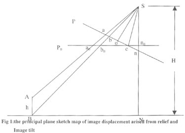
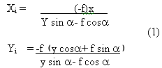
In fig . 1, S is the photographic center, P is titled photograph, Po is the corresponding horizontal photograph, c is the iso center of photograph , A is a ground point with elevation h, B is the projective Point of A in level surface, Sn0=So= principal distance f, image plane coordinate system is set up with its origin c and isometic parallel, principal line as x axes, y axes respectively, A and B are respectively projected to a and b in photograph P, a0 and b0 in photograph P0 ab correspond the images point displacement due to topography undulation, and is denoted by dh, from the relevant knowledge of [1], the coordinate ( x,y) of point b in tilted photograph P with its origin o and the coordinate ( xt, yt ) of point b0 in horizontal photograph P0 with its origin n0 has the relationship:
Where a is the tlt angle of photograph P.
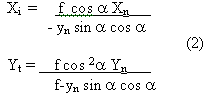
If the tilted photograph origin is translated to photo nadir point n, and the coordinate of b is expressed as ( xn, yn), then x= xn, Yn= y+f tg a , Eqs ( 1) can be written as :
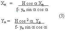
In ground surface, we set up the coordinate system with N as its origin and axes parallel to the axes of photograph plane, the coordinate ( Xn, Yn) of point B and the coordinates ( Xt Yt) of point bo has the relationship : Xt = f Xn / H , Yt = f Yn / H, then :
the length of vector nb is rb = Ö x2 n + Y2 n, where Yn= rb sin F, F is the argument of vector nb , The length of vector Nb can be written as :
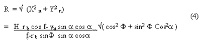
similarly, if we keep other condition unchanged except that we let the A point as the zero height point, a is the corresponding image point of A, ra is the length of vector na , then R can be expressed as :
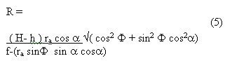
we can obtain the image point displacement dh from Eqs. (4) and (5).
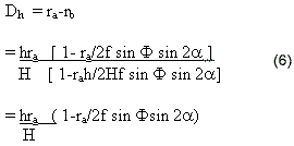
This is the algorithm for determining the image point displacement in oblique photograph with tilt angle a due to topography undulation h, but we must pay attention that ra denotes the length of vector with its origin at photo nadir point.
As to SPOT images, because the filt of photo is not considered , then ( 6) can be written as :
Where, r denotes the distance between image point and image center line, ? is the incidence angle. We differentiate Eqs. (7) to h and ? respectively, the results are :
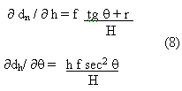
From Eqs. (8) we can conclude that photograph incidence has larger impact on image point displacement than topography undulation, in other words, photographs incidence magnifies the image point displacement from topography undulation, the following table 1 also support this conclusion.
The flight height of SPOT satellite is 822 km, pixel size in image is 13 mm , the photographic scale of PA image and XS image is respectively 1:8000, 000 and 1:400,000, the algorithm to determine displacement Dh in rectified scale form displacement dh in image is :
Dh= dh (m/M) , where m is photographic scale and M is the rectified scale.
For SPOT PA images, ignoring the tilt of photograph, we naturalize the maximum point displacement in image with different incidence angle resulted from topograph undulation to 1:50000 rectified scale, the result is listed in table 1:
Table 1 maximum displacement of SPOT image naturalized to 1:50000 scale due to topographic relief
(unit :mm)
| Underation (m) | Incidence angle ( degree) | ||||||||||
| 0 | 0.6 | 1.2 | 1.8 | 2.4 | 3.6 | 6 | 9 | 12 | 15 | 27 | |
| 100 | 0.07 | 0.09 | 0.11 | 0.13 | 0.16 | 0.20 | 0.28 | 0.39 | 0.50 | 0.61 | 1.09 |
| 200 | 0.14 | 0.19 | 0.23 | 0.27 | 0.31 | 0.40 | 0.56 | 0.78 | 0.99 | 1.22 | 2.18 |
| 300 | 0.22 | 0.28 | 0.34 | 0.40 | 0.47 | 0.59 | 0.85 | 1.17 | 1.49 | 1.82 | 3.27 |
| 400 | 0.29 | 0.37 | 0.46 | 0.54 | 0.62 | 0.79 | 1.13 | 1.56 | 1.99 | 2.43 | 4.36 |
| 500 | 0.36 | 0.47 | 0.57 | 0.67 | 0.78 | 0.99 | 1.41 | 1.94 | 2.49 | 3.04 | 5.46 |
| 600 | 0.43 | 0.56 | 0.68 | 0.81 | 0.94 | 1.19 | 1.69 | 2.33 | 2.98 | 3.65 | 6.55 |
| 700 | 0.50 | 0.65 | 0.80 | 0.94 | 1.09 | 1.39 | 1.98 | 2.72 | 3.48 | 4.26 | 7.64 |
| 800 | 0.58 | 0.74 | 0.91 | 1.08 | 1.25 | 1.58 | 2.26 | 3.11 | 3.98 | 4.86 | 8.73 |
| 900 | 0.65 | 0.84 | 1.03 | 1.21 | 1.40 | 1.78 | 2.54 | 3.50 | 4.48 | 5.47 | 9.82 |
| 1000 | 0.72 | 0.93 | 1.14 | 1.35 | 1.56 | 1.98 | 2.28 | 3.89 | 4.97 | 6.08 | 10.9 |
| 1100 | 0.79 | 1.02 | 1.25 | 1.48 | 1.72 | 2.18 | 3.11 | 4.28 | 5.47 | 6.69 | 12.1 |
| 1200 | 0.87 | 1.12 | 1.37 | 1.62 | 1.87 | 2.38 | 3.39 | 4.67 | 5.97 | 7.30 | 13.1 |
Geometric rectification of SPOT
images
The geometric rectification method usually used includes
polynomial method and differential method [3], which will be discussed
briefly thereinafter
Polynomial rectification
The
fundamental of polynomial rectification is bypassing the spatial relation
of photograph, simulating the geometry distortion with translating,
scaling, rotation, affine, skew and their combination, then presenting the
relationship between original and rectified image using a second order or
third order polynomial rectification is frequently used because its
simplicity and cheapness. Polynomial rectification also can be used to
registrate SPOT images to other sensor image .
From table 1,
we can conclude that SPOT images with zero incidence angle can be
rectified using, polynomial method if topographic undulation is less than
700 m; the acceptable undulation decreases with incidence angle increases;
the SPOT image with >100 incidence angle can't be rectified using
polynomial .
Digital Difference Rectification
for
SPOT images , we set up the image plane coordinate system with its origin
at the center of image and y axis parallel to flight direction, then the
imaging equation of the I row is : 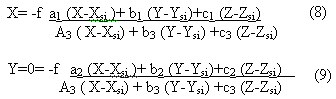
Where, (x, y) is the image point
coordinate, f is the equivalent principal distance, (X, Y, Z) is the
corresponding ground point of (x, y) , Xsi, Ysi,
Zsi are the exterior point elements in 1 row, ai,
bi, ci, (I= 1,2,3,) are the cosine of exterior angle
elements in I row. When rectifying SPOT image, the exterior elements in
center row are calculated through space resection of a single photograph,
we select a point ( X, Y, Z) from Dem grid, substitution of it into eqs
.(9) yield the y value, marking it as yp. the value yp suggest which row
the current point is, combining the row number and the exterior elements
of current row into Eqs. (8) and (9) and get the value ( xl,
yl). If yi is a infinitely small value, then (
x1+y1 +yp) is the corresponding image
coordinates of ( X, Y, Z), else we substitute y1+yp
for yp and calculate new y1, this procedure will
continue until yi is infinitely small .
Digital
differential rectification bases equation and perform point to point
rectification. Theoretically, therefore, any SPOT image can be
differentially rectified with high precis4e, but differential
rectification has disadvantage of computation expensiveness and necessity
of DEM. In fact, we usually have to rectify SPOT images with large
incidence angle in high topographic undulation under the condition of no
DEM to use, which is nearly impossible using polynomial rectification or
differential rectification. We present a new rectification method-point by
point rectification based on offset measurement-to resolve this
problem.
Point by point rectification of SPOT image based
on offset measurement
The essence of geometrical rectification is
to remove the image point displacement, point by point rectification of
SPOT image based on offset measurement is aimed to eliminate the offset
between the corresponding points in SPOT image graphics model which is
generated from scanned topographic map. The main steps are the
following.
- SPOT image course orientation - With SPOT image as the input
image and the corresponding DRG as the reference image, only four
corresponding points are selected, which had better distribute in the
four corners of DRG. Then, one-order polynomial correction is carried
out and the course orientation is finished.
- Measurement of the offset in corresponding points - After
courser orientation, the relative distortion, such as skew and scale, is
left, which mainly results form the topographic, undulation. We
superimpose DRG on to orientated image, search all the corresponding
points which are visible clearly in either image, and measure the
coordinates of these points using mouse. In the range equal to 1:50000
DRG, it is optimal to measure 70-100 points based on the consideration
of the compromise between computation expensiveness and precision of
rectification. All the coordinates of these points and the corresponding
offset values are stored as a text file, which called " offset file
".
- Point by point rectification - for every grid point P=(x,y) in which has been geocoded to a particular projection plane, we inverse it the oriented image grid system by adding a special offset? P=(?x, ?y). to determine the offset ? p, we search for four points in DRG from the offset file which hale the nearest distance to point P1,P2, P3, P4, and the corresponding offset in these points are ? P1, ? P2, ?P4. we interpolate the offset ?P
By
: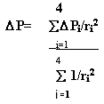
Where
ri denotes the distance form point Pi to point P, of
courser, if point P already in the offset file ? is acquired directly from
offset file. Thus the coarsely oriented image is geo-registerated to the
DRG accurately.
The above algorithm has been developed as a
software which has been successively applied to the National Buerua of
surveying and mapping (NBSM)'s project-generation of 1:50000 satellite
orthoimage.
An experiment has been carried out to check the
precision of point by point rectification based on offset measurement .
the SPOT image for experiment is imaged on Mar, 1999 in Lushan mountain
are with incidence angle 1.90, and the corresponding 1:50000
map index is H50-89-A. the maximum topographic undulation in test area is
1300 meters, the elevation in nearly one fifth are is above 1000 meters,
and the Boying Lake is comprised in this map range, so searching clearly
visible corresponding points is difficult, total 62 offset is measured and
recorded, at last we measured the coordinated of 30 pairs of point the
rectified image and the DRG, the error results are listed in Tab.
2.
Tab.2 precision check of point by point rectification based on
offset measurement ( unit:meter) .
| Point No | Error | Point No | Error | Point No | Error | Point No | Error | Point No | Error | Point No | Error |
| 1 | 12. | 6 | 21.1 | 11 | 13. | 16 | 10. | 21 | 19. | 26 | 18. |
| 2 | 11.6 | 7 | 8.5 | 12 | 22. | 17 | 16. | 22 | 19. | 27 | 13. |
| 3 | 18. | 8 | 5.0 | 13 | 12. | 18 | 8.8 | 23 | 14. | 28 | 26. |
| 4 | 23. | 9 | 31.7 | 14 | 11.6 | 19 | 25. | 24 | 15. | 29 | 7.5 |
| 5 | 7.8 | 10 | 18.8 | 15 | 27. | 20 | 9.5 | 25 | 13. | 30 | 15 |
| Mean square error: 16.8 | |||||||||||
Tab 2. indicates that this rectification method is
feasible.
Conclusion
we formulated point
displacement of SPOT images with different incidence angle due to
topographic undulation, the formulate indicate that oblique viewing angle
magnify the image point displacement from topography relief. The SPOT
image point displacement resulted from 100-1200 meters topography
undulation is calculated and naturalized to 1;50000 scale, the result is
listed in Tab.1. from, the following conclusion can be acquired : if
topography undulation is less than 700 meters; SPOT images with Zero
incidence ( vertically illuminate ground ) can be rectified using
polynomial method; with incidence angel increasing, acceptable topography
undulation becomes small; when incidence angel is above 100, the image is
not appropriate for polynomial rectification. Tab . 1 provides guide to
select proper rectification based on offset measurement is proposed, which
can be used to rectified nadir-off image in large topographic undulation
are, a experiment on this new rectification method is carried out, the
results suggests that the new rectification method is simply and
feasible.
Reference
- Li Deren, Jin Weixuan, You Jianshan , Zhu yixuan, Basic
Photogrammetry. Press of Surveying and Mapping, Beijing, 1995, 1995,
56-60.
- Li Deren, Zhen Zhaobao , Analytical Photogrammetry. Press of
Surveying and Mapping. Beijing, 1992. 413-423.
- Liu Haiyuan.
- Geo Haiyuan. Geometrical Rectification of SPOT images. Journal of
Remote sensing, Beijing, 1998,
15(3):33-35.