| GISdevelopment.net ---> AARS ---> ACRS 1999 ---> Measurement and Modeling |
Semi-Automatic System for
Roof Reconstruction Based on 3D Linear Segments
Shih-Hong Chio and
Shue-Chia Wang
Ph.D. Candidate and Professor, Department of Surveying Engineering,
National Cheng-Kung University
No. 1, University Road, Tainan City, China Taipei
Tel:(+886)-6-2373876 ext.834; Fax:(+886)-6-2375764
E-mail: p6883102@sparc1.cc.ncku.edu.tw
Keywords: Semi-Automatic, Roof Reconstruction,
Object Knowledge, 3-D LinePh.D. Candidate and Professor, Department of Surveying Engineering,
National Cheng-Kung University
No. 1, University Road, Tainan City, China Taipei
Tel:(+886)-6-2373876 ext.834; Fax:(+886)-6-2375764
E-mail: p6883102@sparc1.cc.ncku.edu.tw
Abstract
Up to now, the automatic reconstruction for buildings can’t satisfy all the current requirements. Hence, the problem of roof reconstruction becomes to how to effectively integrate the interpretation ability of the operator into the reconstruction system and help this system to accomplish the task. This paper presents a semi-automatic system for roof reconstruction based on 3-D linear segments by the effective integration of the interpretation ability of the operator. After verifying of the shown 3-D linear segment, the operator selects other 2-D or 3-D lines of roof patch in any image with the mouse device and then decides the reconstruction model to automatically find the equivalent in the other image. We will present three models for roof reconstruction and compare these results. Preliminary experiments prove this framework of this system is feasible and the interface model by the operator is also effective.
Introduction
The general procedure for roof reconstruction could be simply divided into the three subtasks: geometrical feature extraction, the detection of possible locations of roofs or roof boundaries and the final roof reconstruction. Even though the rapid development of the computer technology, it is still a great problem to make the computer deal with the interpretation task correctly. The central point lies on the lack of complete theory to handle this problem as far so that the automatic reconstruction for building[ Collgins et al., 1995;Fischer et al., 1997; Henriccson and Baltsavias, 1997; Lin et al., 1995; McGlone and Shuffel, 1994; Nevatia et al, 1997; Shuffelt 1996] can’t satisfy all the current requirements. Hence, the reconstruction problem becomes to another issue that is how to effectively integrate the interpretation ability of operator into the system and help this system to accomplish the reconstruction correctly, i.e. semi-automatic system for roof reconstruction[ Gruen,1998; Gülch, 1997; Heuel and Nevatia,1995; Hsieh, 1995; Lang and Förstner,1996]. Therefore, this paper would like to present a semi-automatic system for roof reconstruction based on 3-D linear segments by the effective integration of the interpretation ability of the operator. First of all, one 3-D linear segment is verified whether it belongs to the boundaries of roofs or not. Then, the operator selects other 2-D or 3-D lines of this roof patch in one single image with the mouse device. Finally, the system automatically finds the equivalent of this roof patch in the other image after the operator decides the reconstruction model. Of course, the result would be verified by the operator again. The 3-D linear segments verified by the operator play an important role, i.e. to give a constraint information, when conducting the reconstruction. We will present three models for reconstruction and compare these results. Another issue in our paper is to investigate the feasibility of our system in the urban areas and analyze the possible questions. Meanwhile, we also express our opinion about the effective interface model by the operator.
System Design and Illustration
Fig. 1 illustrates the whole diagram of this semi-automatic system. The 3-D linear segments are obtained by considering the object knowledge of 3-D lines in object space when simultaneously linking and matching the 2-D lines from the stereo images with known orientation [Chio et al., 1999]. This algorithm exploits the change rate of height and plane distance to improve the linking of linear feature in the images of urban areas, where might capture the "false" collinear features in image space because of the affection of projection position or occlusion.
Fig.1: Diagram for roof reconstruction
At the beginning of roof reconstruction, the system will display one 3-D linear segment. Then, the operator verifies if the linking result is correct and if this one represents the border of the roof patch or not. If the answer is no, the system will ignore this 3-D linear segment and shows the next one; otherwise, the operator can select other 2-D or 3-D lines, which could consist of the complete roof patch, with the mouse device in any single image. What we need are the intersection points of linear segments to decide the roof corners, therefore, the selected 2-D or 3-D lines could be only a part of one complete roof boundary. Our system now could deal with the quadrangular roof, which is not only limited to parallelism or rectangle, and the selected order should be clockwise or counterclockwise. Moreover, one feature for our system is that the way of line-selection could not be as accurate as the way of point-selection. In this procedure, the recognition ability of the operator is fused into system to correctly choose the borders of roof patch. The selection of lines for roof patch is corresponding to the detection of roof. The advantage of such a handling is to reduce the judgement of computer and compensate for the ability of the computer to identity those roof boundaries from the numerous linear segments.
So far, the lines selected by the operator have formed the roof patch in single image and the intersections of the adjacent lines also could represent the corners of roof patch basically. Note here, one complete roof might consist of only one roof patch or several roof patches. For example, two slope roof patches compose one complete roof. It completely depends on the building construction and the generalization of the operator. All selected lines, besides the first one verified by the operator is a 3-D linear segment, might be pure 2-D linear segments without height information or 2-D lines with height datum, here called 3D lines. The subsequent procedure is to use the first 3-D line with correct height and the corners of roof patch to automatically find the equivalent in the other image. We develop three models for the roof reconstruction by simultaneously taking into account some constraints, e.g. height constraint and epipolar constraint. The operator could choose the optimal result from those three models. Hence, the recognition ability of the operator again is integrated into this system and this handling ensures the result correct. If the final result could not be found by these three models, the last choice is to reconstruct the roof patch by pure manual operation, e.g. point-wise measurements. This reconstruction isn’t stopped until all the roof patches are completed.
Reconstruction Models
After identifying the first 3-D linear segment and completing the selection of other lines of roof patch in one single image, the sequential job is to find the counterpart in the other image based on the roof corner in this image and some constraints. Fist, the system calculates the approximate x-parallax from the midpoint coordinates of the first 3-D linear segment. Because the used image pair are normalized images [Cho and Shenk, 1992], the approximate position of roof patch in the other image can be known along the epipolar line. The system searches the junctions, which are extracted by the method [Föstner, 1994], with the spiral way based on the approximate position. The first reconstruction model is to regard the first junction point as the corresponding roof corner in the other image when proceeding the spiral search way. The second model is to find all candidate junctions within 11*11 window size. Roof corners in single image and their candidate corresponding points could calculate the height by the space intersection. The minimum height difference among these candidate corresponding points and the first 3-D linear segment are the optimal choice in our system.
The first model takes the extracted junctions into consideration. Except for the epipolar and parallax constraints, no space information of roof patch is considered. Regarding of the second model, the heights of corresponding roof corners are limited based on the first 3-D height. Speaking about the third reconstruction model, it searches the corresponding lines on the other image according to the height information of the first 3-D linear segment and the azimuth constraint of this 3-D line on the image pairs during the reconstruction procedure. Of course, the wrong matching and linking 3D linear segments might be verified and corrected in terms of the first 3-D linear segment in this processing. Therefore, the first 3D linear segment will play an important role in this approach. The diagram in Fig. 2 will show more detailed about this model.
Fig.2 Digram of the third reconstruction model
Experiments and Results
Fig. 3 illustrates the test stereo image pairs and the results of the tests. The used images are reduced twice after the original photos were scanned with the resolution of 15 mm. The original photos were taken by the normal angle camera with 60% overlap in Tainan City. After reducing, their image scale is about 1: 8000. Meanwhile, there are two complete roofs in this test area. The topmost consists of the flat roof and other two slope roof patches compose the other gable roof. The two complete roofs are all partly occluded by the frame of flowers on the higher flat roof. Moreover, the higher flat roof also occludes the lower gable roof. Some annexes to the higher flat roof, looking like the roof garden, make the extraction of 2-D linear features broken and uncompleted. Of course, it also makes the linking and matching of 3-D linear segments get the wrong results. In Fig 3, those 3-D lines are displayed with yellow color and 2-D lines with cyan color. The red line prompted by the system means the initial 3-D line for roof reconstruction and the green points represent the junctions extracted by the Förstner extraction algorithm. Blue quadrangles mean the borders of roof patches selected by the operator or found by the reconstruction model. Small pink marks show the roof corners. For the sake of viewing easily, these pink marks have been enlarged.
The rightmost column represents the results of three models for flat roof reconstruction, and the topmost blue quadrangle in this column shows the roof patch picked up by the user. Note here, the selected roof boundaries are not complete 2-D or 3-D lines. Two of three lines are 2-D lines without any height information and the other one is the 3-D line. After verifying the first 3-D line and selecting the relevant 2-D or 3-D lines, the reconstruction results are illustrated in the second, third and fourth row respectively. It can be very clear to view the results from the blue quadrangles that the reconstruction from the third model is better than other two. The reason is that the third modeling exploits much more information from lines than the junction information used in the first and second model. Certainly non-accurate 2-D lines will make the reconstructed results unreliable. The second and third row at the leftmost two columns (i.e., Test I and II) represent the results of the two slope roof patches. Although one line in the Test I is occluded by the frame of flowers and one line in the Test II is not the real boundary of slope roof patch, the results seem good when verifying by the eyes. The occlusion could be a great problem of roof reconstruction in urban areas, it seems the system entitles the preliminary ability to handle this problem.
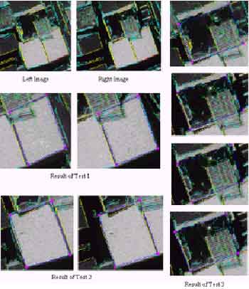
Fig.3 The results of roof reconstruction
Fig.4 shows how the system uses the height information of the first 3-D line to correct the wrong 3-D line. The Rightmost means the roof in right image selected by the operator. And the leftmost blue quadrangle shows the result without checking the height information between the first 3-D line and the selected 3-D line during roof reconstruction by the means of the third model. After checking the height information, the right quadrangle (in middle part of Fig.4) is reconstructed correctly.
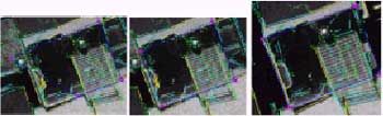
Fig.4: Illustration of the correction result of wrong 3-D line based on the first 3-D line. Rightmost: the selected roof patch; Leftmost: the wrong result; Middle: the correct result.
Conclusion
Although some drawbacks should be improved in our system, the initial results are satisfactory. Therefore, it proves the framework of this system is feasible. Especially this system really integrates the recognition ability of operator into this semi-automatic system, i.e. the verification of the first 3-D line, the selection of other rooflines and the decision of the final results. This consideration really compensates the recognition ability for the computer in order to handle the complicated imaging environment at the urban areas. The future development for our system is to test for the bigger urban area so as to find the possible problems.
References
- Chio, S.-H., Wang, S.-C., and Wrobel, B., 1999. A Semi-Automatic System for the Reconstruction of Building Roofs in Dense Urban Areas Using Aerial Stereo Images Pairs. AVN ALLGEMEINE VERMESSUNGS-NACHRICHTEN, pp.167-174.
- Cho,Woosug and Shenk,Toni, 1992. Resampling Digital Imagery to Epipolar Geometry. Research Activities in Digital Photogrammetry at The Ohio State University: A Collection of Papers Presented At the XVII Congress of ISPRS, Toni Schenk Editor, Department of Geodetic Science and Surveying, The Ohio State University, Columbus, Ohio, pp.37-43.
- Collgins, R.T., Y-Q. Cheng, C. Jaynes, F. Stollw, X. Wang, A.R. Hanson, and E.M. Riseman, 1995. Site Model Acquisition and Extension from Aerial Images. International Conference on Computer Vision, Cambridge, MA, pp.888-893.
- Fischer, A., T.H. Kolbe, and F. Lang, 1997. Integration of 2D and 3D Reasoning for Building Reconstruction Using a Generic Hierarchical Model. W. Förstner and L. Plümer, Editors, Semantic modeling for the acquisition of topographic information from images and maps. Proceedings of Workshop "SMATI '97", pp.159-180, Bonn Bad Godesberg, Birkhäuser Verrlag.
- Förstner, W., 1994. A Framework for Low Level Feature Extraction. J.O. Eklundh, editor, Computer Vision, ECCV ’94, Vol. II, pages 383-394. Lecture Notes in Computer Science, 801, Springer-Verlag, Berlin, 1994.
- Gruen. A., 1998. TOBAGO-a semi-automated approach for the generation of 3-D building models. ISPRS Journal of Photogrammetry & Remote Sensing 53: pp.108-118.
- Gülch. E., 1997. Application of Semi-Automatic Building Acquisition. A. Gruen, E.P. Baltsavias, O. Henricsson, Editors, Automatic Extraction of Man-Made Objects from Aerial and Space Images(II), Birkhäuser Verrlag, Basel.
- Henricsson, O. and E. Baltsavias, 1997. 3-D Building Reconstruction with ARUBA: A Qualitative and Quantitative Evaluation. A. Gruen, E.P. Baltsavias, O. Henricsson, Editors, Automatic Extraction of Man-Made Objects from Aerial and Space Images(II), Birkhäuser Verrlag, Basel,pp.65-76.
- Heuel, S. and R. Nevatia, 1995. Including Interaction in an Automated Modeling System. Proceedings of the IEEE Symposium on Computer Vision, Coral Gables, Florida, pp.383-388.
- Hsieh, Y., 1995. Design and Evaluation of a Semi-Automated Site Modeling System. Technical Report CMU-CS-95-195, School of Computer Science, Carnegie Mellon University, Pittsburgh, Pennsylvania. Lang, F. and W. Förstner, 1996. 3D-City Modeling with a Digital One-Eye Stereo System. International Archives of Photogrammetry and Remote Sensing, Vol. XXXI, Part B3, pp.415-420, Vienna.
- Lin, C., A. Huertas and R. Nevatia, 1995. Detection of Buildings from Monocular Images. A. Gruen, O. Kuebler, P. Agouris, Editors, Automatic Extraction of Man-Made Objects from Aerial and Space Images, Birkhäuser Verrlag, Basel, pp.125-134.
- McGlone, J.C. and J.A. Shuffelt, 1994. Projective and Object Space Geometry for Monocular Building Extraction. Proceedings of IEEE Conference on Computer Vision and Pattern Recognition, pp. 54-61. Nevatia, R., C.Lin and A.Huertas, 1997. A System for Building Detection from Aerial Image. A. Gruen, E.P. Baltsavias, O. Henricsson, Editors, Automatic Extraction of Man-Made Objects from Aerial and Space Images (II), pp.77-86, Birkhäuser Verrlag, Basel.
- Shufelt, J.A., 1996. Projective Geometry and Photometry for Object Detection and Delineation. Ph.D Thesis (Technical Report CMU-CS-96-164), School of Computer Science, Carnegie Mellon University, Pittsburgh.