| GISdevelopment.net ---> AARS ---> ACRS 1999 ---> Measurement and Modeling |
Institute of Geodesy and Photogrammetry
Swiss Federal Institute of Technology ( ETH) Zurich
ETH Honggerberg , CH-8093 Zurich , Switzerland
Tel: 41-1-6333038 Fax: 41-1-631101
E-mail: agruen@geod.ethz.ch, wang@geod.eth.ch
Usually, two important topics are involved in 3-Databases urban information systems, i.e. data acquisition, data management and handling. CyberCity-Modeler (CC-Modeler) is a methodology and a software for the automatic generation of the topology of an unstructured 3-Databases point cloud \, which has been developed in order to generate structured data for city models from photogrammetrically measured points. This paper aims at reporting about the performance of CC-Modeler, but will mainly describe the status of the development of our spatial information system CC-SIS, which is specially designed for the handling of 3-Databases city data and the integration of raster images and vector data in terms of a hybrid GIS.
Introduction
The generation and management of 3-Databases city models became an important issue in the recent past due to the increasing demands for a realistic presentation of the real world. Though different applications may require different data types different data types and manipulation function, the geometrical information to be operated on in a 3-Databases city system usually includes tow types of data : vector data and raster images. An appropriate data model should not only represent the geometrical information, but also implicitly or explicitly describe the topological relationship between geometrical objects . in this case of texture mapping, it also must have the must have the ability to manipulate raster images. The complexity of spatial objects and the verity of data types. Especially 3-Databases objects and images as tow completely different data types, makes it a challenging task develop a 3-Databases spatial model and data structure for the purpose at hand. At the institute of Geodesy and Photogrammetry, ETH Zurich, two research topics treated by our group are : (a) the generation of the topology of 3-Databases object by using Photogrammetric tools, and 9b) the investigation of the data model and the development of a system t manage the vector data and raster images based on relational data base technology. A detailed technical description of the former problem is addressed in Gruen, Wang, 1998 with our CC- Modeler ( CyberCity Modeler ). Here , we will present a technology for the management of data, which is implemented in our CC-SIS ( CyberCity Spatial Information system).
CC-Modeler
Photogrammetry is an appropriate tool to provide information about man-made objects, vegetate cover and the like. Recently, many approaches for automated and semi-automated extraction of buildings and roads from aerial images have been proposed ( Gruen et al., 1997) Due to the complexity of natural scenes and the lack of performance of image understanding algorithms, the fully automated methods cannot grantee results stable and reliable enough for practical use ( Gruen et al ., 1997). Therefore, we have developed a semi-automated approach, which gives the human operator strong computational support in order to generate 3-Databases city models from aerial images efficiently.
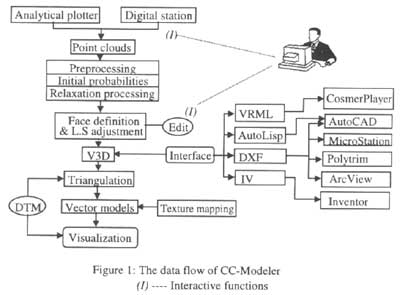
with CC-Modeler ( CyberCity Modeler ) were present a new method for fitting planar structure to measured sets of point clouds. In CC- Modeler , the feature identification and measurement is implemented in manual mode, on an a Analytical Plotter or a Digital Station. During the data acquisition, 3-Databases points belonging to a single object are coded into two different types according to their functionality and structure : boundary points and interior points. CC-Modeler is an automatic topology generator for 3-Databases objects . the main components of the system are shown in figure 1. the first obligatory step is preprocessing. Which includes the checking of the measurement order of the boundary points 9 BP), detection of redundant points, and determination of the possible groups of faces, based on sets of\adjacent ( BP) point pairs.
Table 1: CC-Modeler statistics of projects
| Project | Total No. of Roof units | Structured interactively | Structured interactively | Failures | CPU time (sec) |
| Zurich Center | 4729 | 4487 | 240 | 2 | 1493 |
| Zuric standelhofen | 553 | 534 | 19 | 0 | 184 |
| Orelikon | 7253 | 6971 | 279 | 3 | 2089 |
| Melbourne university | 1136 | 1104 | 32 | 0 | 313 |
| ETH Hoenggerberg | 172 | 170 | 2 | 0 | 53 |
| Dretikon | 298 | 290 | 8 | 0 | 56 |
| Regensdorf | 925 | 894 | 30 | 1 | 165 |
| Giessen | 4157 | 4117 | 40 | 0 | 1213 |
| Firenze center | 1544 | 1509 | 33 | 2 | 504 |
| Total | 20767 | 20076 | 683 | 8 | 6070 |
The next step is to build the face model of the 3-Databases object,
i.e. to determine how many faces the 3-Databases object has\, which points
define an exact face and the spatial relations of the faces. This is
implemented through a consistent labeling algorithm by probabilistic
relaxation operations, in which two procedures are involved, the initial
probability determination and the relaxation processing. The result of
consistent labeling is the face definition for every face. Then, least
squares adjustment is performed for all faces simultaneously, fitting the
individual faces in an optimal way to the measured points and considering
the fact that individual points are usually members of more that one face.
This adjustment is amended by observation equations that model orthogonal
constraints of pairs of straight lines between boundary points. The
details of these algorithms are presented in Gruen, Wang, 1998. Finally, a
vector description of 3-Databases objects is obtained, which is
represented in a self-developed data structure ( V3D). 
CC- Modeler has been
successfully implemented on workstations ( Sun SPARC) under X Windows and
OSF/ Motif, and has been tested in several projects. The statistics of
those data sets are presented in Table 1. ' Structured automatically "
refers to the number of roof units that CC-Modeler builds successfully
with full automatic processing, and " Structured interactively" refers to
the number of roof units that needed to the manually modified in some
faces. Obviously, the success rate of CC-Modeler's automatic processing is
better that 95% and almost al roof units can be constructed by using the
convenient editing tools. The main reason of CC-Modeler failing to process
an object is that the measured point cloud was incorrectly coded. The main
reasons for editing are measurement errors and ambiguities in topological
relations.
For the visualization and animation of the data sets we
use various software : AutoCAD Micro station, Inventor, and Polytrim.
Figure 2 Shows a view of the city model' Zurich Center " created with
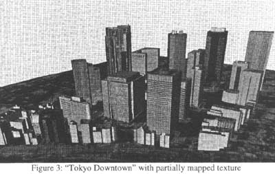
Micro Station, including building, rivers, trees and DTM. For photo
realistic rendering were combine the vector data of the building and the
DTM with images raster data. The raster images are taken from aerial
images. Figure 3 shows the city model of " Tokyo Downtown " with the
result of mapping image data onto the DTM and some walls and roofs.
Data Structure
V3D is a hybrid data structure. It not
only models 3-Databases objects, but also combines raster images and
attribute information for each object. The terrain objects are grouped
into four different geomatic object types : Point Objects , Line Objects,
Surface Objects and Body Objects in V3D, each special object is identified
by Type identifier Code ( TIC), referred to as PIC, LIC ,. SIC and BIC,
respectively. Tow data sets are attached to each object type: thematic
data and geometric data. The images data can be attached to the surface
object, body object and DTM object . in fact, the thematic data attributes
are built up in a separate data table. It is linked to the object type
with a related class label. The definition of the thematic data is
user-dependent.
The geometric data set contains the geometric
information of 3-Databases objects, i.e. the information of position,
shape, size, structure definition ,and image index. The diagram in Fig. 4
shows the logical data structure . 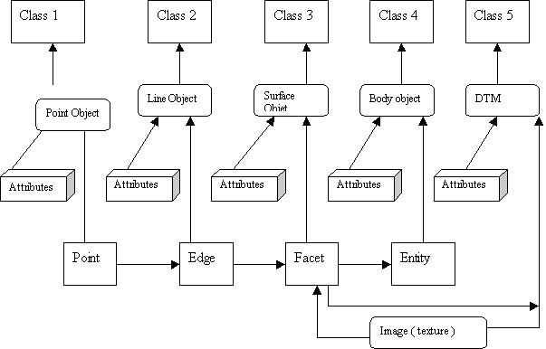
Figure 4: the logical data
structures of V3D
For the four object types, four geometrical
elements are designed . i.e. Point, Edge, facet and Entity, Point is the
basic geometric elements in the diagram. The Point can present a point
object. It also can be the begin or end point of an Edge. The edge is a
line segment which is an ordered connection between two points: begin
point and end point. Further, it can be a straight part of a line object
or lie on a facet. The facet is the intermediate geometrical element it is
completely described by the ordered edges that define the border of the
facet. One or more facts can be related to a surface object or Entity
geometrical element. Moreover , facet is related to an image patch. Entity
is the highest level geometrical element, and it can carry shape
information. An entity is completely defined by its bordering facts.
Images data and thematic data are two special data sets. Which are built
up in tow separated data tables. Each facet is always related to an image
patch through a corresponding link.
Once the attribute table is
attached and the TIC is labeled, a geometrical element becomes an object
type . the DTM is treated as a special data type. Which is described by a
series of facets.
Obviously, the topological relationships between
geometrical elements are implicitly defined by the data structure. A point
object is presented by a distinct Point element. The line object is
described by ordered Edges. The surface object is described by the facet
with the informations of image Patches. Similarly, the body object is
described by Entity that are defined by the facets. Thus the topological
relationships between Point and Edges. Edges and Facet, Facet and Entity
are registered by the links between the geometrical elements.
Implementation in A Relational Database
In a relational
database the most common object to be manipulated is the relation table.
Other objects such as index, views, sequence, synonyms and data dictionary
are usually used for query and data access. " Table " is the basic storage
structure, which is a two -dimensional matrix consisting of columns and
rows of data elements. Each row in a table contains the information needed
to describe one instance of the entity , each column represents an
attribute of the entity. The data model shown in figure 4 is a logical
model, which can be implemented by relational data base technology. Figure
5 shows the relational model of the V3D data structure. 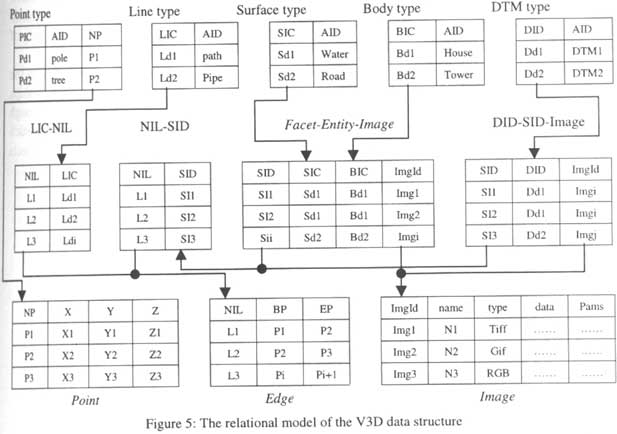
Each object type is
defined as a table , shown as the upper row. A point type table includes
three terms. The point Identification Code ( PIC) is an identification
code for a point type object. The attribute identification (AID) is coded
the relate an attribute table. Different types of objects may have
different attribute tables. For example the te attribute tables of " tree"
may have different thematic definitions than " pole ". The Name of Point
(NP) is the identification of a geometric point. Which is used to relate
it with a distinct element in a point geometric element. The point table
is the most basic geometrical element table , which defines the coordinate
position of the geometrical points.
The line type table has
similar content as the point type table. The difference is that a line
type object is identified by the Line identification Code ( LIC) which is
not directly linked with the geometric element table Edge, but linked with
an intermediate relational table LIC-NIL and then indexed to the Edge
table. The Edge table defines the geometrical element edge, in which each
edge ( NIL) is described by the beginning point ( BP) and the end point
(EP). The surface type table and body type table have similar terms as the
line type table. For each type of object a distinct identification code (
SIC or BIC) is labeled. . both ISC and BIC are linked with a merging
geometrical element table, Facet and Entity, Facet and Image are defined.
Facet-Entity-Image table has tow links; one is related to the Image table;
the other is related to the NIL-SID table. Image table is a basic table,
which describes all attributes of images, such as athe image name, format,
pixel, Camera parameters, orientation parameters etc. the NIL-SID table is
another intermediate table, which defines the corresponding relationships
between Facet and Edge. Its NIL column is related to the Edge table. The
DTM is treated as a special class, which is related to the NIL-SID table
through an intermediate table DID-SID-image.
Based on the
relational structure shown on the diagram in Figure 5, the query of a
geometrical description of a distinct object type is easily realized. For
example, the query " Select the geometrical description of an object with
the identification code BIC =202", will first index all Facet
identification in the Facet-Entity-Image table by its BIC, and then get
all edge name identification ( NIL ) , Finally index the position
information of structure points with the help of Edge table and Point
table.
The queries of topological relationships are divided into
tow types; relationships between the geometrical elements of an object and
those between objects themselves. The relationships between the
geometrical elements are implicitly defined in the above data structure.
Though the internal topology is not directly supplied, users can flexibly
deduce the relationships, such as joi8jnt, adjacency, left or right, etc.
the queries of topological relationships between objects are not
considered in the above data structure because they are
application-dependent. 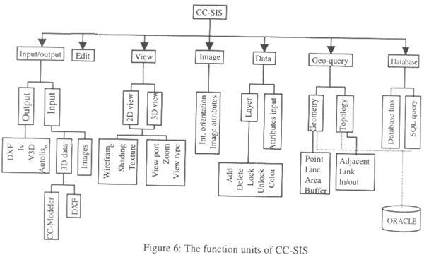
Prototype System
Based on the above data model
and structure, a spatial information system, CC-SIS, has been successfully
developed and implemented on a workstation ( Sun SPARC ) under X-window,
and ORACLE datable . the seven function units of CC-SIS are shown in the
Figure 6. it can directly handle the data file generated by CC- Modeler
and DXF. The edit function is used for graphic editing, which is to be
developed in the future. The view port, zooming, etc. further, three types
of rendering are also available , wireframe, shading and texture mapping.
The image function supplies the tools for interior orientation of the
images in order to map natural texture form image. An example of this
function is shown in figure. 7. 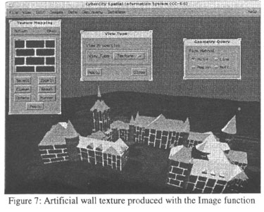
The manipulation of data
is supplied by the Data function. It includes tow sub-modules; one is used
for the operation on layers ; the other is to input the attributes for the
selected object . the Geo-query function includes tow tools: geometry
query and topology query and topology query. The former is used to query
the separated object by the point, line or entity selection ; the latter
is employed to query topological relationships between different objects .
figure 8 shows the geometric query of CC-SIS . the user can mark an object
( e.g building ) with a cursor . thus triggers and displays the
corresponding attributes an geometrical/topological information. The
operations on a database are defined in the Database function, including
database link and SQL- query. SQL-query is a sub-menu, in which standard
SQL queries are supplied. 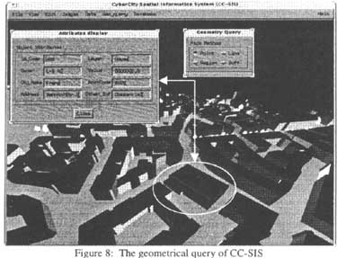
Conclusion
CC-Modeler is a powerful data
acquisition tool for the generation of 3-D city models. Our experiments
shows, that it is flexble, robust and accurate . in several projects we
have achieved a success rate of better that 95% percent in fully automated
structuring. Remaining problems are indicated and can be solved
interactively. We have developed our own data structure V3D wit interfaces
to a variety of CAD and visualization packages. CC-Modeler cannot only
reconstruct multiple kinds of 3-D objects such as buildings, waterways,
roads, trees, DTM, etc. but also map images onto these objects. This can
be combined with data from general land use, communication systems,
utilities, property and administrative boundaries, etc. to generate a
complete 3-D city model.
Given an efficient method for 3-D data
acquisition, the generation of a powerful 3-D spatial information system
becomes even more mandatory. Our prototype system CC-SIS ( CyberCity
Spatial information system ) has proven to represent a suitable concept
which is worth developing further.
Based on our proprietary V3D
vector data structure, a relational data base has been created. The data
to be operated on can be logically separated into vector data, image and
thematic information. I this paper the focus is on the geometrical part of
the database ( vector data and images. ) our pilot application show that
V3D is a suitable structure for the representation of 3-D objects, images
and thematic data. it is possible the answer most of the questions about
topology, position and shape of objects by means of geometric or SQL
queries.
References
- Gruen, A., Wang, X., 1998, " CC-Modeler: a topology generator for 3-D city models", int. Archives of Photogrammetry and Remote sensing, Vol. 32, Part 4 , pp 188-196.
- Gruen, A., Baltsavias, E., Hericsson, O., ( eds), 1997. Automated extraction of a man-made objects form aerial and space images (II). Procedings of athe Monte Vertia Workshop, May 1997, Brikhause Verlag, Basel.