| GISdevelopment.net ---> AARS ---> ACRS 1999 ---> Geology |
Radar Image for the Study of
Landslide Structures in HK
Shi Huosheng, Lin Hui
Joint Laboratory for Geoinformation Science
The Chinese University of Hong Kong
Tel: (852)26098105 Fax: (852)26037470
E-Mail:(hsshi,huilin)@cuhk.edu.hk
Joint Laboratory for Geoinformation Science
The Chinese University of Hong Kong
Tel: (852)26098105 Fax: (852)26037470
E-Mail:(hsshi,huilin)@cuhk.edu.hk
Keywords Landslide Radar image Subordinate shear
plans Micro-geography
Abstract
Hong Kong Radar Image provides us lots of detail information of subordinate shear planes. These low-grade shear planes are very important factors of landslide. By image procession and field investigation, we find that subordinate shear planes often make rock lose bulking property, displays unbalance feature, and expedite the development of landslide. In processed radar image, subordinate shear planes which can be traced are R planes, P planes and R’ shear planes. These subordinate shear planes are close related to the evolution of micro-geography, and also to the development of landslide. Affected by the regional N45E strike-slip fault, the subordinate N60E dextral shear planes formed at the direction of P shear plan, the N30E dextral shear plans formed at the direction of R shear plan, and the NW faults formed at the direction of R’ direction. The boulder falls landslide can only be formed at the extension fault direction of R shear plan, and the alluvium gravity landslide formed at N60E shear direction.
1. Geology setting
1.1 The rock exposed
The working area is around Jubilee Reservoir. The main exposed rock around Jubilee Reservoir is fine-grain granite with weak pink color, granodiorite, and pyroclastic rock with some lava. Rocks are strongly weathered along fault zone, especially at the area of tensely distributed joints or faults.
1.2 The structure frame
The faults are well developed nearby the Jubilee Reservoir(JR, Fig.1). Three fault sets can be traced: NE, NW, and EW. The NE trend faults are usually parallel to the long direction of Tolo Harbor, which was considered as the offset of Lianhua Shan regional fault zone(Bennet,1984, C.F.Lee,1998, Fletcher,1997,Y.Z.Ding,1997). The NW trend faults can be divided into two types: regional faults and subordinate faults. The regional NW faults have large scale and can be easily recognized on radar image. It usually cut through the whole mountain area and shows a regular lineation. The subordinate faults are in small scale, usually performed as structural lamellae and restricted in-between the regional faults. In radar image, both NE and NW fault can be traced at three scales. The first scale includes the elongation direction of mountain, the shoreline and the shape of harbors. The second scale includes the local topography, the distribution of valley and streamlet, and the middle scale lineations. The third scale includes the joints and the micro-topography, they display as image lamellae and the regular digital zones in processed image.
1.3 The subordinate shear plans
The subordinate shear plans which can be traced are R plans, P plans and R’ plans. R shear plan has close relation to micro-topography and to image lamellae. It located at the tense and shear junction has strongly damaged the bulking property of rocks during it development. R shear plan usually formed at the side of NE fault with 15 degrees, and has the same sinistral movement as NE fault(Batlett,1981, Lu Huafu,1998,Shi Huosheng,1996). The shape of Jubilee Reservoir itself can be represented as a combination of transtensional structures . The recent landslide was occurred at the pure tense boundary. The deep valley, at the south end of Jubilee Reservoir, has impressive of structural significance. The steep slopes together with R shear plan and the tense boundary are the most important factors of boulder falls land slide in this area. R’ shear plan is against the move direction of main shear plan, called anti-movement shear plan, and exhibits itself as a fault or shear joint. R’ plan exhibits the distribution of sinistral shear set in main fault zone of dextral movement, and exhibits the distribution of dextral shear set in main fault zone of sinistral movement. P shear plan located at the direction of N60E, where is easy to form the alluvium gravity land slide.
2. Subordinate shear plans and Landslide
2.1 Image procession
The Radar image used here was made by Chinese Academy of Science, which parameters are in table 1. Synthesis Aperture Radar image can give a strong stereoscopic view and very rich information on texture, which are helpful to show the features of linear structure(Armin Gruen,1997,Chen Shupeng,1998,Guo Huadong.1991). For such merits, it is widely used in the study of geological structure. However, SAR image has noticeable speckle noise which need a filter processing. Based on the analysis and comparing of several noise removing methods, we choose K-self-adaptive filter which has a better result for such a process. In addition, because SAR and TM use different way to receive different band range of spectrum of ground features, they have obvious difference on showing the characteristics of spectrum of objects on the ground(Pang Xizhe,1996). If these two image sources combined together, they can reveal the characteristics of objects on the ground and information of subordinate structure to a great extent. In order to compose the monochromatic SAR image and multi-spectrum color image, we make ISH transformation on the color composite image of TM3, TM4 and TM5 bands at first. After that, we use filtered SAR image to substitute for I component. Then make invert-IHS transformation on that. Continually, make KL transformation on TM 3, TM 4, TM 5 and SAR. At last, we do color composite on TM4 image, G component that comes from invert-IHS transformation and the first component from KL transformation to get the final result. Studying on the final image, we found that the subordinate information has been considerably enhanced and the characteristics of both radar and multi-spectrum images have been reflected, and that will provide great convenience for geology interpretation(Fig.1).
Fig.1 Radar Image with processed results (scale bar is 2000 m)
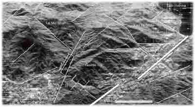
Table 1. The Parameters of Hong Kong Radar Image
2.2 Digital Cross Section
The Digital Cross Section Profile is based on the 3-D graphics of Shing Mun Country Park produced by the 3-D geo-referenced visualization system, Geo3Dvision, developed by our research group, we can get the digital cross section profile A-B by using the function of cross section analysis of Geo3D vision ( Figure 2, A,B are marked on Fig.1). The digital cross section profile then can be used as a basic map to support the interpretation of all geological layers and faults with the integration of other geological material and our observing and analyzing results. In this phase, all interpretation outcomes are described on papers. ArcView is finally employed to digitize the paper-based cross section A-B, and edit symbols of varied geological layers, blocks and faults. As a result, a 2-D data file including the cross section profile, geological layers, and faults, as well as a 2-D map could be obtained. Moreover, the 2-D data of the cross section A-B can be incorporated into the web based virtual environment for 3-D display and analysis after the coordinate transformation from 2-D coordinate system to 3-D system. From the digital cross section, we can easily get the land surface information and the geology information. The faults showed in the cross section mainly depend on the subordinate shear plans. The other abbreviations represent crystal tuff with biotite(JTM), vitric tuff with fiamme(JAC), siltstone and mudstone(SL), crystal tuff and tuff breccia(JSM), granodiorite(GD), fine-grained granite(GF).
Fig. 2 Digital Cross Section A-B
2.3 Structure composition
The movement of strike slip fault can produce a subordinate stress field and form a set of subordinate structural surfaces(Fig.3). Based on the results of image procession, we recognized the subordinate structures surfaces of R-shear plan. R’-shear plan. P-shear plan in study area, and the micro pull-apart structure in the direction of R shear plan has structure records in Jubilee Reservoir region. R-shear plans are with a smaller acute angle a 1 to the main shear plan Y (doted line in Fig.3). The angle a 1 is equal to half of angle . , the inner friction angle of rock. The value of a 1 is about 8°~20°, and the angle direction represent the move direction of inside block. R plan can be a fault or joint of shear plan, it has same movement as the main fault. R plan exhibits the distribution of sinistral shear set in main fault zone of dextral movement, and exhibits the distribution of dextral shear set in main fault zone of sinistral movement. R’ shear plan is with a larger acute angle a2 to the main shear plan Y. The angle °2 is equal to 90° minus j/2, the angle direction represent the move direction of inside block. The shear direction of plan R’ is against the move direction of main shear plan, called anti-movement shear plan, and exhibits itself as a fault or shear joint. R ’ plan exhibits the distribution of sinistral shear set in main fault zone of dextral movement, and exhibits the distribution of dextral shear set in main fault zone of sinistral movement. The shear plans R’ and R are a couple of conjugate shear plans of subordinate stress field. P shear plan is with a smaller acute angle ß1 to the main shear plan Y. The angle ß1 is equal to j/2. The angle direction indicates the move direction of outside block. P plan exhibits itself as fault or shear joint, move direction is same as plan Y, called syn-movement shear plan. P plan exhibits the distribution of dextral shear set in main fault zone of dextral movement, and exhibits the distribution of sinistral shear set in main fault zone of sinistral movement. The newly formed land slide located at the SE side of Jubilee Reservoir, that is R’ shear plan in NW direction.
Fig.3 The subordinate shear planes in shear zone
R- Riedel shear plane R'- Negative riedel
3. The relationship between land slides and subordinate structures
3.1 The structure controlled micro-geography
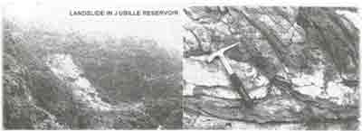
Study area has many valleys and steep slops, so the outcrops are comparable rich. The changes of micro geography are exactly reflecting the distribution of subordinate shear plans. On the northern slop of Needle Hill, a serials P shear plans regularly distributed in NNE, formed the land surface as shape of rhombus and formed the Duplex Structure locally. It is a typical feature of high strain area. The sharp end of the land slopes are the record of former weathering and erosion, the positions of S shaped image texture and the brightness quick change are the possible positions of produce land slides. Fig.4(left) clearly show that the transtension structure is the control factor of producing landslide, especially when the subordinate shear planes change dip angle at depth(right). There are no brittle bent deformations in study area, so the plan deformations are well recorded by radar image. Because radar wave has strong capacity of detect lineation, the possibility of recording the R, P, R’ shear plans is largely increased. By selecting the weak information of lineations in radar image, we can recognize rich subordinate joints. Almost all of these joints are of structure significance, so the error can be largely avoided during the structure analyze.
Fig.4 Map of landslide and its structural backgound (See text for detailes)
3.2 Search landslide in radar image
The image procession not enhanced the feature of subordinate structures, and also reserved the main regional faults. This increased the systemic interpretation of radar image, and is favorable to apply the broken theory. By field examination, the most of lineation image are subordinate shear plans, which have significant feature of structure deformation.
3.3 Field data of landslide
The subordinate transtension structures in Jubilee Reservoir was also based on the field data. The granite there is strongly weathered, and the base rock is regular exposed. The NE dextral shear plans are: 30 / 120 < 80.20 / 110 < 78, represented by the heavy joints belt. The NW tension plan is 346 / 256 < 88, where existed a deep valley. On the north edge of the valley, there is a newly formed land slide. So, under the movement of N45E strike-slip fault, we can figure out that N60E dextral shear plans located at the direction of P shear plan, N30E dextral shear plans located at the direction of R shear plan, and the NW faults located at the direction of R’ direction. This composition controlled the different scale of boulder falls land slide in NW extension fault direction, and the alluvium gravity land slide in N60E shear direction.
3.4 Acknowledgement
This project support from Hong Kong Research Grand Committee (CUHK 4334/98E) and Hong Kong Industry Supporting Fund (AF/169/98). The 308 subject of 863 Project made the Radar image of Hong Kong.
References
Abstract
Hong Kong Radar Image provides us lots of detail information of subordinate shear planes. These low-grade shear planes are very important factors of landslide. By image procession and field investigation, we find that subordinate shear planes often make rock lose bulking property, displays unbalance feature, and expedite the development of landslide. In processed radar image, subordinate shear planes which can be traced are R planes, P planes and R’ shear planes. These subordinate shear planes are close related to the evolution of micro-geography, and also to the development of landslide. Affected by the regional N45E strike-slip fault, the subordinate N60E dextral shear planes formed at the direction of P shear plan, the N30E dextral shear plans formed at the direction of R shear plan, and the NW faults formed at the direction of R’ direction. The boulder falls landslide can only be formed at the extension fault direction of R shear plan, and the alluvium gravity landslide formed at N60E shear direction.
1. Geology setting
1.1 The rock exposed
The working area is around Jubilee Reservoir. The main exposed rock around Jubilee Reservoir is fine-grain granite with weak pink color, granodiorite, and pyroclastic rock with some lava. Rocks are strongly weathered along fault zone, especially at the area of tensely distributed joints or faults.
1.2 The structure frame
The faults are well developed nearby the Jubilee Reservoir(JR, Fig.1). Three fault sets can be traced: NE, NW, and EW. The NE trend faults are usually parallel to the long direction of Tolo Harbor, which was considered as the offset of Lianhua Shan regional fault zone(Bennet,1984, C.F.Lee,1998, Fletcher,1997,Y.Z.Ding,1997). The NW trend faults can be divided into two types: regional faults and subordinate faults. The regional NW faults have large scale and can be easily recognized on radar image. It usually cut through the whole mountain area and shows a regular lineation. The subordinate faults are in small scale, usually performed as structural lamellae and restricted in-between the regional faults. In radar image, both NE and NW fault can be traced at three scales. The first scale includes the elongation direction of mountain, the shoreline and the shape of harbors. The second scale includes the local topography, the distribution of valley and streamlet, and the middle scale lineations. The third scale includes the joints and the micro-topography, they display as image lamellae and the regular digital zones in processed image.
1.3 The subordinate shear plans
The subordinate shear plans which can be traced are R plans, P plans and R’ plans. R shear plan has close relation to micro-topography and to image lamellae. It located at the tense and shear junction has strongly damaged the bulking property of rocks during it development. R shear plan usually formed at the side of NE fault with 15 degrees, and has the same sinistral movement as NE fault(Batlett,1981, Lu Huafu,1998,Shi Huosheng,1996). The shape of Jubilee Reservoir itself can be represented as a combination of transtensional structures . The recent landslide was occurred at the pure tense boundary. The deep valley, at the south end of Jubilee Reservoir, has impressive of structural significance. The steep slopes together with R shear plan and the tense boundary are the most important factors of boulder falls land slide in this area. R’ shear plan is against the move direction of main shear plan, called anti-movement shear plan, and exhibits itself as a fault or shear joint. R’ plan exhibits the distribution of sinistral shear set in main fault zone of dextral movement, and exhibits the distribution of dextral shear set in main fault zone of sinistral movement. P shear plan located at the direction of N60E, where is easy to form the alluvium gravity land slide.
2. Subordinate shear plans and Landslide
2.1 Image procession
The Radar image used here was made by Chinese Academy of Science, which parameters are in table 1. Synthesis Aperture Radar image can give a strong stereoscopic view and very rich information on texture, which are helpful to show the features of linear structure(Armin Gruen,1997,Chen Shupeng,1998,Guo Huadong.1991). For such merits, it is widely used in the study of geological structure. However, SAR image has noticeable speckle noise which need a filter processing. Based on the analysis and comparing of several noise removing methods, we choose K-self-adaptive filter which has a better result for such a process. In addition, because SAR and TM use different way to receive different band range of spectrum of ground features, they have obvious difference on showing the characteristics of spectrum of objects on the ground(Pang Xizhe,1996). If these two image sources combined together, they can reveal the characteristics of objects on the ground and information of subordinate structure to a great extent. In order to compose the monochromatic SAR image and multi-spectrum color image, we make ISH transformation on the color composite image of TM3, TM4 and TM5 bands at first. After that, we use filtered SAR image to substitute for I component. Then make invert-IHS transformation on that. Continually, make KL transformation on TM 3, TM 4, TM 5 and SAR. At last, we do color composite on TM4 image, G component that comes from invert-IHS transformation and the first component from KL transformation to get the final result. Studying on the final image, we found that the subordinate information has been considerably enhanced and the characteristics of both radar and multi-spectrum images have been reflected, and that will provide great convenience for geology interpretation(Fig.1).
Fig.1 Radar Image with processed results (scale bar is 2000 m)
Table 1. The Parameters of Hong Kong Radar Image
| Date of flight | Sep. 18, 1998 | Sep. 19, 1998 |
| Site Name | Hong Kong, China | Hong kong, China |
| SAR Band | L | L |
| Transmit Polarization | H | H |
| Receive Polarization | H | H |
| Line Spacing (m) | 6.25000000 | 6.25000000 |
| Pixel Spacing (m) | 6.25000000 | 6.25000000 |
| Height of Flight(m) | 8400 | 8400 |
2.2 Digital Cross Section
The Digital Cross Section Profile is based on the 3-D graphics of Shing Mun Country Park produced by the 3-D geo-referenced visualization system, Geo3Dvision, developed by our research group, we can get the digital cross section profile A-B by using the function of cross section analysis of Geo3D vision ( Figure 2, A,B are marked on Fig.1). The digital cross section profile then can be used as a basic map to support the interpretation of all geological layers and faults with the integration of other geological material and our observing and analyzing results. In this phase, all interpretation outcomes are described on papers. ArcView is finally employed to digitize the paper-based cross section A-B, and edit symbols of varied geological layers, blocks and faults. As a result, a 2-D data file including the cross section profile, geological layers, and faults, as well as a 2-D map could be obtained. Moreover, the 2-D data of the cross section A-B can be incorporated into the web based virtual environment for 3-D display and analysis after the coordinate transformation from 2-D coordinate system to 3-D system. From the digital cross section, we can easily get the land surface information and the geology information. The faults showed in the cross section mainly depend on the subordinate shear plans. The other abbreviations represent crystal tuff with biotite(JTM), vitric tuff with fiamme(JAC), siltstone and mudstone(SL), crystal tuff and tuff breccia(JSM), granodiorite(GD), fine-grained granite(GF).
Fig. 2 Digital Cross Section A-B
2.3 Structure composition
The movement of strike slip fault can produce a subordinate stress field and form a set of subordinate structural surfaces(Fig.3). Based on the results of image procession, we recognized the subordinate structures surfaces of R-shear plan. R’-shear plan. P-shear plan in study area, and the micro pull-apart structure in the direction of R shear plan has structure records in Jubilee Reservoir region. R-shear plans are with a smaller acute angle a 1 to the main shear plan Y (doted line in Fig.3). The angle a 1 is equal to half of angle . , the inner friction angle of rock. The value of a 1 is about 8°~20°, and the angle direction represent the move direction of inside block. R plan can be a fault or joint of shear plan, it has same movement as the main fault. R plan exhibits the distribution of sinistral shear set in main fault zone of dextral movement, and exhibits the distribution of dextral shear set in main fault zone of sinistral movement. R’ shear plan is with a larger acute angle a2 to the main shear plan Y. The angle °2 is equal to 90° minus j/2, the angle direction represent the move direction of inside block. The shear direction of plan R’ is against the move direction of main shear plan, called anti-movement shear plan, and exhibits itself as a fault or shear joint. R ’ plan exhibits the distribution of sinistral shear set in main fault zone of dextral movement, and exhibits the distribution of dextral shear set in main fault zone of sinistral movement. The shear plans R’ and R are a couple of conjugate shear plans of subordinate stress field. P shear plan is with a smaller acute angle ß1 to the main shear plan Y. The angle ß1 is equal to j/2. The angle direction indicates the move direction of outside block. P plan exhibits itself as fault or shear joint, move direction is same as plan Y, called syn-movement shear plan. P plan exhibits the distribution of dextral shear set in main fault zone of dextral movement, and exhibits the distribution of sinistral shear set in main fault zone of sinistral movement. The newly formed land slide located at the SE side of Jubilee Reservoir, that is R’ shear plan in NW direction.
Fig.3 The subordinate shear planes in shear zone
R- Riedel shear plane R'- Negative riedel
3. The relationship between land slides and subordinate structures
3.1 The structure controlled micro-geography
Study area has many valleys and steep slops, so the outcrops are comparable rich. The changes of micro geography are exactly reflecting the distribution of subordinate shear plans. On the northern slop of Needle Hill, a serials P shear plans regularly distributed in NNE, formed the land surface as shape of rhombus and formed the Duplex Structure locally. It is a typical feature of high strain area. The sharp end of the land slopes are the record of former weathering and erosion, the positions of S shaped image texture and the brightness quick change are the possible positions of produce land slides. Fig.4(left) clearly show that the transtension structure is the control factor of producing landslide, especially when the subordinate shear planes change dip angle at depth(right). There are no brittle bent deformations in study area, so the plan deformations are well recorded by radar image. Because radar wave has strong capacity of detect lineation, the possibility of recording the R, P, R’ shear plans is largely increased. By selecting the weak information of lineations in radar image, we can recognize rich subordinate joints. Almost all of these joints are of structure significance, so the error can be largely avoided during the structure analyze.
Fig.4 Map of landslide and its structural backgound (See text for detailes)
3.2 Search landslide in radar image
The image procession not enhanced the feature of subordinate structures, and also reserved the main regional faults. This increased the systemic interpretation of radar image, and is favorable to apply the broken theory. By field examination, the most of lineation image are subordinate shear plans, which have significant feature of structure deformation.
3.3 Field data of landslide
The subordinate transtension structures in Jubilee Reservoir was also based on the field data. The granite there is strongly weathered, and the base rock is regular exposed. The NE dextral shear plans are: 30 / 120 < 80.20 / 110 < 78, represented by the heavy joints belt. The NW tension plan is 346 / 256 < 88, where existed a deep valley. On the north edge of the valley, there is a newly formed land slide. So, under the movement of N45E strike-slip fault, we can figure out that N60E dextral shear plans located at the direction of P shear plan, N30E dextral shear plans located at the direction of R shear plan, and the NW faults located at the direction of R’ direction. This composition controlled the different scale of boulder falls land slide in NW extension fault direction, and the alluvium gravity land slide in N60E shear direction.
3.4 Acknowledgement
This project support from Hong Kong Research Grand Committee (CUHK 4334/98E) and Hong Kong Industry Supporting Fund (AF/169/98). The 308 subject of 863 Project made the Radar image of Hong Kong.
References
- Armin Gruen and Haihong Li, 1997,Semi-Automatic Linear Feacher Extraction by Dynamic Programming and LSB-Snakes, Photogrammetric Engineering & Remote Sensing,Vol.63,No.8,August ,pp985-995
- Batlett, W.L., Friedman, M. and Logan, J.M., 1981, Experimental folding and faulting of rocks under confining pressure, Tectonophysics, vol.79, pp.255-277
- Bennet, J.D., 1984, Review of tectonic history, structure and metamorphism of Hong Kong, Geotechnical Control Office, 6/84
- C.F.Lee, Chen Hong, 1997, Landslides in Hong Kong: Causes and Prevention, Acta Geo-Graphica Sinica, Vol.52, Supplement, pp.114-121 (in Chinese with English Abstract)