| GISdevelopment.net ---> AARS ---> ACRS 1999 ---> Airborne Remote Sensing |
Development of Airborne 3D
Imager
Li Shukai, You
Hongjian
(Institute of Remote Sensing Applications, Chinese Academy of Sciences , Beijing 100101)
Zhang Chonghou
(Institute of Geography, Chinese Academy of Sciences, Beijing 100101)
Keywords: laser range-finder,
multi-spectral imaging, integrated technology system.
(Institute of Remote Sensing Applications, Chinese Academy of Sciences , Beijing 100101)
Zhang Chonghou
(Institute of Geography, Chinese Academy of Sciences, Beijing 100101)
Abstract
A new airborne remote sensing system, airborne 3D imager supported by Chinese High-Tech Plan is presented in this paper, and this 3D imager is developed by institute of Remote Sensing Applications, Chinese Academy of Sciences and Shanghai Institute of Technology Physics, Chinese Academy of Sciences. Optical-mechanical scanning laser range-finder, multi-spectral scanning imager, Global Positioning System (GPS), INS/GPS combined attitude measurement unit and special synchronization match technology are used to design this airborne remote sensing integrated technology system based on aerial ranging principle. Quasi 2D laser ranging points matched image pixels which are called point couples are densely distributed in remote sensing image and those point couples can be directly used to calculated their geographical coordinates (X, Y,Z) according to aerial ranging principle. Then remoter sensing image can be processed into geo-referenced image matched with DEM through simply fitting and interpolating. The result of some fights tests show that it is a high efficient airborne remote sensing integration system which can generate above results without ground control point (GCP) or with only a few GCPs. This result improves efficiency up to 10 ~100 times higher than traditional technology, and it becomes an important remote sensing technology of the future.
The principle and technology structure of this technology system are briefly introduced in this paper, and the result of some flight tests and its characters are also given. The development and application fields of this technology system are analyzed in the end.
1. Introduction
Environment, resources and population have been the focus problems of body. It is now being well known that our earth should be regarded as a united "earth system", the earth environment where people live should be researched in global scale, regional scale or national scale based on the earth system science. Digital earth, digital Asia and digital Asia and digital China should be set up. All kinds of change, models and comprehensive models which influences the living environment should also be set up in order to guide the human being to adjust their activities to the nature, and then earth environment can be protected and develop. Earth observation technology, an important to understand the nature, should meet the requirement of society and it should be also develop and innovate continuously. Meeting the requirement of the society is the development source of earth observation technology.
There are many remote sensors and observation modes in present earth observation systems because there are many different application fields and different technology conditions and some others factors, and they are still being developed. Stereo observation system, laser ranging & multi-spectral imaging coupled system, interfere SAR are the main earth observation systems which can be get the spectral information of the targets and 3D terrain information simultaneously.
Stereo observation system has being developed and improved for nearly 100 years. Now it is experiencing an innovated change from analog image to digital image and from ground-to-air positioning principle to air-to-ground positioning principle. Today stereo observation system is a universal advanced mapping technology is every country of the world, and some satellite-borne and airborne earth observation systems still uses stereo observation mode. Laser ranging & multi-spectral imager coupled system (Airborne 3D imager) was proposed eight years ago and its prototype was developed three years ago. Conic scanning airborne system was finished recently, and its accuracy has reached the 1:10000 scale mapping criteria. Similar satellite borne system is to be developed. Interfere SAR (InSAR) is an all-weather earth observation system belonging to microwave. Both satellite-borne InSAR and airborne InSAR have the ability to acquire 3D terrain information. But it will take some time to be developed into a commercial technology system.
The first systems are optical remote sensing while the latter one is microwave remote sensing. They are three different technology systems with different principle, different advantage, different spectrum and different technology. Many technologies are integrated into each technology system, especially the Airborne 3D Imager and InSAR integrate many high technologies. The system that is to be get multispectral information and 3D terrain information simultaneously is the development trend of the future.
2. Principle and System Structure
2.1 Principle
2..1.1 Basic equation
assuming there is a vector OP, when the coordination of the start point O (Xo, Yo, Zo), the slope range of the vector S and the attitude of the vector (f, w, k) are known, then the geographical coordinate of terminal point can determined precisely according to following formula:
Where (Xo, Yo, Zo) is the center of the remote sensing determined by global Positioning System (GPS) receiver, (f, w, k) are three attitude parameters provided by high accurate attitude measurement unit (AMU) and slope S is measured by high rate laser range finder without reflector.
2.1.2 Laser point matching image pixel
Optical mechanical scanning multi-spectral imager uses a rotate mirror controlled by coder to generate image. in this system, scanning laser rangefield and scanner use the same optical system. Both the laser and scanner are controlled by the coder. The coder drives the scanner continuously to acquire the spectral information while the coder drive the laser rangefield to measure the slope range per fixed several pixel. Because of using the same optical system, the laser point matches pixel every several pixel in the image. Figure 1 shows how the laser points are distributed in the image.
2.1.3 Time synchronization of the system
The synchronization of the different component is realized through coder. When the scanner scans to the nadir, the code will generate a pulse and this pulse then drive the GPS receiver to generate a time mark. The position of the remote sensing (Xo, Yo, Zo) is Interpolated according to this time mark from the regulated GPS positions. At the same time this pulse will also drive the AMU to provide the instantaneous attitude of the scanner. That means (f, w, k) is know.
2.14 Rigid connection of the system
The AMU, scanner and laser rangefinder are all mounted in a rigid plate. There is a fixed vector between the antenna of GPS and the center of the scanner and this vector can be surveyed precisely through feasible method.
2.1.5 Two scanning modes
According to different application, either line scanning mode or conic scanning mode can be used. These two modes have been finished. Line scanning mode can be applied in remote sensing thematic mapping while conic scanning mode can be applied in complex terrain and acquiring 3D urban building and some other fields.
Figure 1. Distribution of Laser Points and Pixels
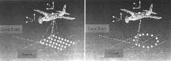
Figure 2 Illustration of Line Scanning Mode and Conic Scanning Mode.
2.2 System Structure
According to above principle, the system is composed of high rate laser, remote sensor, GPS receiver and attitude measurement unit.

Fig. 3: System Structure.
3. Flight and Results Analysis
After the airborne 3D imager was developed, many flight tests including prototype flight tests and engineering prototype flight tests have been conducted. After the flight data were processed, field surveying using GPS receivers has been done in order to compare the surveyed results with the processed results by 3D imager, 20 well-distributed ground points were checked and the ratio mean square error is Mx=1.94m , My=1.76m, Mz=).40m.
The first-class products of this system are : (1) Digital Elevation Model (DEM) or contour map referenced map (Figure 6). The second-class products will be: (1) 3D perspective map: (2) remote sensing thematic map; (3) all kinds of application products including measuring and display function.
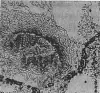 Fig. 4: DEM or Contour map |
 Fig. 5 geoinference image. |
 Fig. 6 Topographic georeferenced image |
4. Distinctive Character and Development Prediction
4.1 The distinctive character
(1) DEM matching geo-referenced image precisely.
It is necessary to apply topographic correction in processing the remote sensing image and it will take three procedures to do this correction using traditional remote sensing technology showed as figure 7.
In 3D imager, Dem matches geo-inference image precisely and they are generated simultaneously through hardware and software. Figure 8 shows the flow chart of the 3D imager.
Fig. 7 The flow chart to generate Topographic Image Map by Traditional Technology.
Fig 8 The Flow Chart to Generate Topographic Image Map By 3D Imager.
(2) Remote Sensing image is geo-inferenced precisely without ground control points or with only several ground control points. Therefore, it will save a lot of time to survey the ground control points in the field.
(3) High efficiency. The 3D imager will improve the operation efficiency 10~100 times than higher than the traditional technology. The reasons are follows:
- The exterior orientation parameters are given precisely. The image is geo-inferenced based on the know parameters acquired during the flight and this is called air-to-ground positioning mode.
- The math formula of geometry principle is very simple.
- Range-image coupled remote senor uses the same optical system and uses coder-driven pulse synchronization technology, which makes the image pixel and laser ranging point synchronize in position and time.
- Positioning and qualitative function are both improved and integrated into one system. The object recognition ability of imagine spectrometer is high, but it will take a complex procedure to position the image. SPOT has the ability of 3D surveying, but its band is small and its object recognition ability is limited. The positioning and qualitative ability are enhanced in 3D imager, therefore the operation efficiency is improved.
Unlike the traditional remote sensing, 3D imager is a new airborne remote sensing system using different principle, and it is also a surveying system. Its distinctive characters show that it is also a high efficient system. It is mainly applied in remote sensing thematic mapping. The price of this system to generate thematic information products is almost the same as the traditional airborne remote sensing.
The multi-spectral scanner of 3D imager may be designed to include 8~16 bands , and it may also be designed into a imaging spectrometer in order to enhance its qualitative function. Therefore, it is possible to develop a high automatic, positioning and qualitative ability integrated airborne remote sensing system. It is possible to improve the accuracy of GPS, attitude measurement unit and laser range finder. Therefore, with the help of restrict checking technology, it is feasible that the accuracy of the image and 3D topographic mapping can reach the accuracy the accuracy of 1:5000 and even 1:2000 scale thematic mapping.
In addition to the application fields like the traditional remote sensing technology system, 3D imager can also be applied in many fields, such as high dynamic monitoring area (engineering process of some projects, special economy area and urban), environment resources investigation (for instance, investigation in desert, islands), difficult area by stereo observation and military environment resources with a high efficiency is the development trend of the future.
5. Reference
- Li Shukai, Xue Yongqi, Airborne laser ranging and Multispectral Imaging Mapping System, Journal of Wuhan Technical University of Surveying and Mapping, No, 4 Vol.4, 1998, pp.340-344.