| GISdevelopment.net ---> AARS ---> ACRS 1999 ---> Airborne Remote Sensing |
High Spectral Resolution
Airborne Optical Sensor
Wang Jianyu, Xue, Yongqi,
Wang Binyong, Xiao Jincai
(Shanghai Institute of Technical Physics, Chinese Academy of Science, Shanghai, 200083, China)
Introduction(Shanghai Institute of Technical Physics, Chinese Academy of Science, Shanghai, 200083, China)
The advanced remote sensing instrument of the new generation ---- Imaging Spectrometer combines the spectrometer technology with the traditional two- dimensional imaging remote sensing technology to form a three-dimensional instrument for remote sensing. While detecting the spatial characteristics of the target with imaging technology, imaging spectrometer disperses each spatial pixel into several tens, or even several hundreds of spectral channels of 10nm bandwidth with spectral technology. The features of ground target can ten be determined through analysis of the spectral characteristic from the image data. It is the great advantage of the high spectral resolution of imaging spectrometer that remote sensing technology initiates completely new application prospects in geo-science.
China has large territory and rich natural resources. The remote sensing technology is bound to play an important role in the country. SITP works on remote sensing instruments for more than 20 years and has developed a series of practical airborne imaging spectrometers. Supports by government high technology plan (863 plan), an advanced airborne earth observation system will be developed in the end of 2000. The system will be equipped with high spectral resolution imaging spectrometer, high spatial resolution camera, 3-dimension imaging and advanced SAR and will be used to resource and environment investigation, remote sensing. Operative Modular airborne Imaging Spectrometer (OMIS) and Wide -view CCD Pushbroom Hyperspectral Imagery (WPHI) consist of the high spectral resolution optical sensors. OMIS and WPHI now are developing in Shanghai Institute of Technical Physics and Shanghai Xiantong Institute of Information Technology.
2 Operative Modular Airborne Imaging Spectrometer (OMIS)
2.1 System Design of OMIS
OMIS is a new generation optical mechanical scanning imaging spectrometer which developing in SITP and SXIIT. The design of OMIS system is based on the linear array detector addition to optical mechanical scanner. The system includes scanning unit, imaging optical unit, spectrometer units, data collection and record unit, monitoring unit, gyrostabilizer platform, GPS and ground system. The specification of OMIS is listed in table 1. Figure 1 is the stereoscopic drawing of OMIS. The characteristics of OMIS are as follows:
The number of bands in OMIS is 128. There are 64 bands in visible/near infrared region, 8 bands in short-wave infrared I region, 32 bands in short-wave infrared II region, 8 bands in middle infrared region and 8 bands in thermal infrared. Five spectrometers are designed to cover total spectral wavelength from 0.45 to 12 mn, They are visible/near infrared spectrometer, short-wave infrared I spectrometer, short-wave infrared II spectrometer, middle infrared spectrometer, thermal infrared spectrometer. The total field of view of OMIS is larger than 70°. OMIS has two operating modes. There are 128 bands and 3mrad IFOV in high Spectral Mode. A Mode B is high spatial resolution mode. The number of bands in mode B is 50 and the IFOV of mode B is as high as 1.5 mrad. The scanning unit, imaging unit and spectrometers are designed as special modules. Different specification of the system can be arranged by combing different modules. A special gyrostabilizer platform is designed in OMIS's system to adapt low high level flying aircraft and to improve the quality of image. The stability of the system is better than half pixel. A high quality difference GPS system is used in OMIS system. Positioning accuracy is better than 10 meter. Based on the radiation and spectral calibration in laboratory and onboard, the system can support the calibration data.
| MODEL A | MODEL B | ||||
| Band: | 128 | Band: | 64 | ||
| (0.4-1.1mm) | 64 | (0.4-1.1mm) | 60 | ||
| (1.1-2.0mm) | 16 | (1.55-1.75mm) | 1 | ||
| (3-5 mm) | 32 | 2.08-2.35mm) | 1 | ||
| (8-12 mm) | 8 | (8-12mm) | 1 | ||
| Spectral Interval: | 10 nm | (V/NIR) | Spectral Interval: | 10 nm | (V/NIR) |
| 50 nm | (SWIR1) | 200 nm | (SWIRI) | ||
| 15 nm | (SWIR2) | 270 nm | (SWIR2) | ||
| 250 nm | (MIR) | 2000 nm | (SWIR2) | ||
| 500 nm | (TIR) | 4000 nm | (MIR) | ||
| IFOV: | 3 mrad | IFOV: | 1.5 -3 mrad | (TIR) | |
| TFOV: | 78 degree | TFOV: | 78 degree | ||
| Scan Rate: | 10-20 lines/sec | Scan Rate: | 10-20 lines/sec | ||
| Optical Aperture | 200 mm | Optical Aperture | 200mm | ||
| Pixel per Line: | 512 | Pixel per Line: | 512 | ||
| Data Encode : | 12 bit | Data Encode: | 12 bit | ||
| Data rate: | 5.12 Mbps | Data rate: | 5.12 Mbps | ||
| Detector: | 64-Element Si | (V/NIR) | Detector: | 64-Element Si | (V/NIR) |
| 8-Element InGasAs | (SWIRI) | 1-Element InGaAs | (SWIR) | ||
| 32-Element InSb | (SWIR2) | InSb & MCT 2- Colour | (MIR & TIR) | ||
| 8-Element InSb | (MIR) | ||||
| 8-Element MCT | (TIR) | ||||
| NEDr | 0.2%-0.5% | NEDr | 0.2 % -0.5% | ||
| NEDT | 0.2-1.OK | NEDT | 0.2K | ||
Fig. 1 The Stereoscopic Drawing of OMIS
2.2 Optical Unit of OMIS
The main optical system of OMIS adapts ht large aperture 45 degress rotating mirror. The optical aperture of OMIS's main optical system is 200mm. For raising optical efficiency and reducing number of parts, the main optical system I consists of a 200 mm aperture parabolic mirror and a 45 degree reflection mirror. Using the shield area of the main optical system I, the second main optical system is designed which consists of two 45 degree reflection mirrors and a parabolic mirror. The second main optical system and spectrometer II completed imaging and dispersing of the short-wave infrared region I (1.0-2.0mm).
Apart from the spectrometer II, three beam splitters are used in all other spectrometers. First beam splitter separates Visible/near Infrared Spectrometer and other three spectrometers. The second beam splitter is used to separate the short-wave infrared spectrometer and other two. Last beam splitter disperses the middle infrared spectrometer and the thermal infrared spectrometer. The blazing gratings are used as dispersive part in all spectrometers. Fig 2 is the optical system diagram of OMIS. The parameters in main optical system are listed below.
| SCANNING MIRROR | ELLIPSE WITH LONG AXIS 282.8 MM & SHORT AXIS 200MM | ||
| Main System: | Main mirror 1 | (parabolic) | f=270mm D=20mm |
| Main mirror 2 | (off-axis parabolic) | f=200mm D=90mm | |
| Field stop | F0.81 mm (3mrad) | ||
| FO.81 mm(1.5mrad) | |||
Fig. 2 The Optical Architecture of OMIS
2.3 Onboard Electronics System of OMIS Data Acquisition System :
The onboard electronics system of OMIS consists of Signal Preamplifier, Data Acquisition System, Recording System and Real-time Monitoring System. Parallel analog signals from the detectors are amplified by the multi-channel pre-amplifier and then are converted to the appropriate digital signal by A/D. The data formatter converts the multi-channel data to a uniform format and sends the data to recording system. To the systematic data acquisition system has the following specifications.
| CHANNEL : | 128 |
| Digits: | 12 bit |
| Sampling Rate: | 128 channels, each channel sampled every 25-50us |
| Analog Input | 128parallel Analog Signals |
| Digital Output | Two 12bit Parallel Prots |
| Instant Data Rate: | 81.92 Mbps (each pixel 16 bit) |
| Average Data Rate: | 20.48 Mbps (each pixel 16 bit) |
| Analog Band width: | 20.92 khz |
Data Recording System : Two 8mm EXByte8900 digital tape recorders are used for Real-time data record in OMIS. They can record total 128 channels' data for** hours in two cassette. The large capacity hard disk system also can be used for real-time data record, because the controller of the record system is based on personal computer.
3. Wide-view Pushbroom Hyperspectral Imagery (WPHI)
3.1 System Design of WPHI
Based on the Pushbroom Hyperspectral Imagery (PHI), which has been designed and manufactured in Shanghai Institute of Technical Physics and Shanghai Xiantong Institute of Information Technology, a Wide-view Pushbrooom Hyperspectral Imagery (WPHI) is being developed. Two cooled area array CCD cameras are used to increase the ratio of signal to noise and enlarge the total field of view of the system. The main specifications of SPHI are listed on table 4.
| SPECTRAL RANGE: | 394 NM ~891 NM |
| The number of wave band: | 244 |
| Spectral sampling: | 1/8 nm |
| Spectral resolution: | 2 nm (best) |
| FOV | 42° |
| Spatial sampling: | 376x2 pixel/line |
| Density of spatial sampling | 1.0 mrad |
| Spatial resolution | 1.5 mrad |
| Data quantification level | 12 bit |
| Quantification rate | 7.2 msample/sec |
4.2 Optical System of WPHI
Wide-view Pushroom Hyperspectral Imagery has no mechanism FOV scan unit, so the FOV of imaging optical unit is all the FOV of imaging, belonging to large FOV system. If reflective optical system is chosen, there is no aberration and high optical emendation of aberration processing of large FOV so that the system doesn't accord with the demands of spectral resolution. So WPHI has refractive optical system. Compared with specially designed lens, the objective lens of camera have ripe techniques high performance-price ratio steady quality. After measurement of aberration and optical penetrative rate it proves that the system meets the demands. Thus three refractive system of instruments all adopt fixed Nikon lens.
In order to fasten the researching speed and reduce cost, we chose two TC241 frame conversion CCD manufactured by TEXAS INSTRUMENT as detectors. The detector has 753hx 244v active elements, special dimension consisting of 753 elements. But the size of active elements is 11.5 x 9mm, difference between the horizontal and the vertical. If an active element corresponds with image cell on the ground, it leads to different resolution between horizontal and vertical. Therefore sampling rate of horizontal image cell should be reduce to half, namely outputs of two active elements incorporate into the one. Since the equivalent size of active element is 23 x 9mm, the horizontal spectral resolution and the vertical are identical spectral resolution and the vertical are identical on the whole. At the same time the signal sampling rate also reduces to half, so that noisy band is decreased and the burden of A/D conversion is lightened.
The optical system diagram of WPHI is shown in fig 3. According to requirements of the FOV, IFOV, spectral revolution, imaging lens, collimating lens, assemble lens, F-number, aperture, plane reflective grating and imaging slot, all parameters are designed and balanced. The parameters of optical system are as follow.
| Objective Lens: | Focus 24mm | f2.0 ~ 22 (adjustable) |
| Collimation Lens: | Focus 50mm | fl.2 |
| Converging Lens: | Focus 50mm | f.4 |
| Gratting: | Groove 2001/mm |
4.3 Onboard Electronics System of PHI
Electronics system includes signal amplifying circuit, A/D conversion circuit data buffer circuit recording and displaying devices and power.. The analog circuit is easy to be disturbed and signal to noise ratio (SNR) goes down. So analog circuit and A/D conversion circuits are incorporated into one signal process module attached on optical head. To be conveniently placed on aboard, it is connected with the digital circuit by cables.
The signal process module manages to amplify the vide signal from CCD video and adjust voltage in order to meet the A/D measurement. To reduce noise, a low-pass is added. In order to improve compatibility, the electronics module with standard PC bus is applied thus makes it faster, cheaper and better in development.
The data buffer card in the computer stores data from the signal process module and meets A/D output rate and computer read rate. It maps to the computer memory. I/O operation selects data page and sends interrupt application at the field synchronization period. The capability of the data buffer card is 128Kbyte, while image data is 1Kbyte each band per line. So the maximal storage is 128 bands per field. The storage ability of data is determined by storage device. For example, EXBTyte-8500 tape recorder can store 30 bands and EXByte-8900 tape recorder can do 128 bands.
5. The Application of the Imaging Spectrometers
The detecting ability of imaging spectrometer has drawn wide attention of both domestic and foreign wide attention of both domestic and foreign academic circles of remote sensing technology, geology and geography. With the development and the consistent improvement of the Instrument, OMIS, PHI has actively participated in many remote sensing projects in China and abroad, for the purposes of Geology, Mineral Resources, Oil Exploration, Marine Resources, Environmental Investigation, Urban Districts Plan, etc. Figure 4 is a single band image of PHI, which is the survey of Hongzhuang airport in ChangZhou. Figure 5 is a single band image of OMIS, which is the survey of Tai lake in Wuxi.
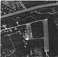
Fig4. Image of HongZhuang Airport, ChangZhou from PHI
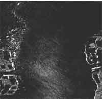
Fig5 Image of Tai lake, WuXi from OMIS