| GISdevelopment.net ---> AARS ---> ACRS 1998 ---> Oceanography/Meteorology |
Coastal Zone Monitoring with
RADARSAT-1
Gordon C. Staples, Jeff
Hurely, and R. Shawan Burns
RADARSAT International
Richmond, B.C., CANADA
Fax 1-604-231-4940
E-mail : gstaples@rsi.ca
AbstractRADARSAT International
Richmond, B.C., CANADA
Fax 1-604-231-4940
E-mail : gstaples@rsi.ca
Coastal zone application of RADARSAT imagery include monitoring of land-use and land-use change, ship sureillance of sovereignty control and fisheries management, detection of oil slicks due to shipping accidents and natural oil seeps, flood monitoring, ocean feature detection, and coastal mapping. The focus monitoring, ocean feature detection, and coastal mapping. The focus of this paper is on a subset of these applications, namely aquaculture detection, coastline mapping, ship surveillance and oil spill monitoring. Optimal conditions for aquaculture detection, coastline mapping, and ship surveillance are large incidence angles and no-wind. In the case of aquaculture detection, imagery acquired under similar wind conditions indicated that the aquaculture notes were using a large incidence angle. In contrast, oil spill detection is optimized at small incidence angles and moderate wind speeds. However, a study of the 1997 Nakhodka oil spill indicated that oil detection was primarily dependent on wind speed and to a lesser degree on incidence angle.
1.Introduction
A large percentage of the world's population and industrial activity is concentrated along the coastal zone. These environmentally sensitive areas are under intense pressure from natural processes, urban growth, resources development, and pollution. These events, originating from both anthropogenic and natural sources, are highly dynamic, and effective monitoring is ideally suited to synthetic aperture radar (SAR) satellite Earth observation techniques because of the synoptic coverage provided, and the ability of SAR to provide reliable monitoring independent of light and weather conditions. Within the context of radar monitoring of the coastal zone, applications of RADARSAT SAR imagery include monitoring of land-use and land-use change, ship surveillance for sovereignty control and fisheries management, detection of oil slicks due to shipping accidents and natural oil seeps, flood monitoring, ocean feature detection, and coastal mapping. The focus of this paper is on a subset of coastal zone application , namely coastal zone land use with a specific emphasis on aquaculture detection, coastline mapping, ship sureveillance, and oil spill monitoring.
RADARSAT represents a new tool for coastal zone monitoring and is viable for applications where traditional optical sensors have met with limited success. While RADARSAT employs a single frequency SAR sensor, it offers many benefits either as a Stand along source of information or in conjunction with multi-spectral system addition, through the use of on-board tape recorders and a world-wide network of ground stations, RADARSAT has capability to provide near-real-time (NRT) data delivery for time sensitive monitoring applications such as ship surveillance, flooding, and oil spill detection.
2.0 RADARSAT SAR
The operational focus of the planned five-year RADARSAT-1 program (a seven-year life-span is projected) is in contrast to other spaceborne SAR programs (ERS and NASA for example) which have a strong research focus. One of the initial objectives for the RADARSAT mission was for ice monitoring, but early in the spacecraft design period, the utility of the RADARSAT SAR was realized and the mission was expanded to include the development of world-wide operational applications.
RADARSAT is equipped with a C-band (5.6 cm wavelength) horizontally-polarized (HH SAR (Raney et al., 1991). The orbit, which is sun-synchronous, near polar, with a 800 km nominal altitude, was configured to give a maximum SAR on-time of approximately 28 minutes per orbit (one orbit is about 108 minutes). Unique to RADARSAT, and the cornerstone for coastal zone monitoring application development, is the availability of user-selectable beam modes via electronic steering of the SAR antenna. RADARSAT has seven beam modes that span a range of incidence angles from 10°C in the near range ot 60oC in the far range.
A given RADARSAT beam mode is defined by a range of incidence angles resolution, and spatial coverage. For example, the Fine mode has a range of incidence angles from 36 to 48 degrees, 8 m nominal resolution, and a 50 km nominal swath width. In contrast, ScanSAR Wide has a range of incidence angles from 20 to 50 degrees, 100 m resolution, and a 500 km swath width. Although RADARSAT's variable beam modes can be exploited to provide imaging at a variety of resolution's there is a trade-off between high resolution and spatial coverage: high resolution coverage is available at the expense of reduced spatial coverage, and similarly, increased spatial coverage is available at the expense of resolution. Therefore, depending on the particular application, beam mode selection can be optimized for a given application.
3.0 Coastal Zone Monitoring
3.1 Coastal Zone Land Use
Encompssing the area that extends offshore to the edge of the continental shelf and inshore to the extent of tidal influence, coastal zones are key areas of economic and biological diversity, affected by both natural and anthropogenic processes. For developed countries, coastal zone management programs are established, with activities such as urban expansion, coastal erosion/accretion, and biological processes routinely monitored.In addition, regions are heavy ship traffic are continually monitored for the presence of oil slicks, both from illegal dumping of oil and accidental oil spills.
In the case of developing countries, eager to implement coastal zone management plants a balance must be struck between economic growth through exploitation of the coastal zone resources and maintenance of coastal zone biodiversity. This dichotomy is evident in many areas of the world where economic expansion and the development of coastal zone resources are pronounced. For example, low-typing coastal regions are prime areas for mangrove forests which are biologically diverse and important natural fish-rearing grounds, but at the same time are key areas for the development of aquaculture sites.
RADARSAT Standard mode imagery (25 m nominal resolution) of Songkhla Lake, Thailand, acquired November 15th, and 18th., 1996, clearly showed the benefit of RADARSAT's variable incidence angle, and how the correct choice of incidence angle was selected to enhance a given application. The November 15 image (Fig. 1 ) was acquired in Standard mode 2 (24° -31° incidence angle range and the November 18 (Fig. 2 image was acquired in Standard 7 (45° -49° incidence angle range). Water borne aquaculture nets (left side of image), which, due to small incidence angle, were not visible in the Standard 2 image, were clearly evident when imaged at the larger incidence angle of Standard 7. In contrast, there was evidence of water-slick discrimination in the Standard 2 image (center of image), but at the larger incidence angle of Standard 7, evidence of water-slick discrimination was not observed. Meteorological data were acquired during both acquisitions, and wind speed, which is a key factor for discrimination of water-surface features, was in the 2m/s -3m/s range.
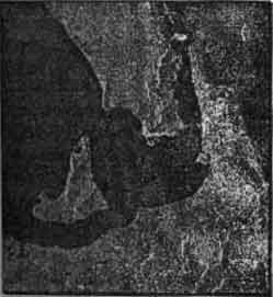
Figure 1. Standard 2 Subscene (12km x 12km) Songkhla Lake, Thailand acquired November 15,1996. Surface slicks are visible in the central part of the image. © Candian space Agency/Agence spatiale canadienne 1996.
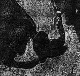
Figure 2. Standard 2 Subscene (12km x 12km) of Songkhla Lake, Thailand acquired November 18,1996Aquaculture nets are visible in the left-hand side of the image © Canadian space Agency/Agence spatiale canadienne 1996.
3.2 Coastline Mapping
Australia is currently developing a GIS-based maritime boundaries information system. O key interest in the system is coastline mapping, and RADARSAT imagery, both Fine beam (8 m nominal resolution) and Standard beam (25 m nominal resolution) was used to evaluate the potential of RADARSAT for this application. Imagery was acquired at the lowest astronomical tide (LAT); the LAT is used to establish territorial sea baseline.
A fundamental issue of this study was the difference in information content of the two beam modes. Resolution proved to be the biggest advantage of the fine beam compared with Standard beam. The Fine beam permitted increased accuracy of the shoreline delineation (Fig. 3). For both beams, it was possible to detect the land-water interface to about 203 pixels. The variance in land-water discrimination translates into 16-24 meter Standard mode and 6-9 meters for Fine beam. Another consideration the incidence angle. Both scenes in this study had a relatively large (>40oC) incidence angle which is optimal for land-water discrimination. However, the choice of incidence angle may depend on acquiring imagery at high or low tide, and the choice of an optimal incidence angle may not be an option.
In addition to the choice of beam mode and incidence angle, the morphology of the shoreline was also an a factor in the land-water delineation. Radar does not penetrate water, but the presence of offshore reefs can be detected and potentially cause confusion between the actual coastline and the reef. The presence of a reef can be detected if the between the actual coastline and the reef. The presence of a reef can be detected if the reef, at low tide for example, protrudes from the water, or the reef may be submerged at all tide levels, but still detected due to radar sensing the breaking waves. As the wave approach the reef and break, the turbulent water increase the surface roughness relative to the (smoother) surrounding water.
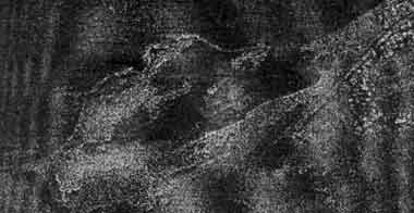
Fig. 3. Fine mode RADARSAT subscene (5 km x 9 km) acquired January 9, 1998. Delineation of the territorial sea based on image acquisition at lowest astronomical tide.
3.3 Ship Surveillance
The juxtaposition of the heavy exploitation of available fish stocks, the paucity of new sources of supply in the wild capture fisheries, and the increasing demand for seafood has placed a premium on the access to sources of fish and shellfish around the world. Numerous countries have established Exclusive Economic Zones (EEZ), quotas, limited entry, and other management systems to protect the inherent value of these living resources, but legislation and regulations cannot by themselves control access to valuable fish stocks and deter illegal fishing activity.
Effective fisheries management strategies must be supported by an meaningful surveillance program (Freeberg et al., 1995). To date, these surveillance programs have relied on conventional methods such as patrol vessels and aircraft. The cost and limited spatial coverage of conventional systems has, however, restricted their effectives as a countermeasure against poaching and non-legal fishing operations. RADARSAT, as a component of a comprehensive fisheries surveillance program, provides wide-area surveillance using ScanSAR mode, or high resolution imaging using Fine mode. RADARSAT has been proven as an effective solution for fisheries surveillance in numerous vessel detection validation studies.
RADARSAT imagery was successfully used for a ship detection validation study off the west coast of Canada using 50 m ScanSAR Narrow imagery (Staples et al., 1997). Vessels including tug and barge combinations, fishing boats, and passenger ferries were detected. The smallest vessel detected was a fishing boat with a length of 27 m, and the largest was a bulk carrier with length of 225 m. For fisheries monitoring, the size of the smallest detectable vessel is of more concern than the size of the largest detectable vessel. The focus of much of the ship detection research using RADARSAT is on the establishment of the minimum detectable ship length as a function of beam mode, incidence angle, wind speed, and other ship parameters (Vachon et al., 1997).
A dramatic example of the capability of RADARSAT to detect target (ships and oil rigs in this case) and oil slicks was evident in the Wide 1 image of the Persian Gulf acquired February 18, 1998 (Fig. 4). A second image was acquired on February 28 and used to discriminate ships and oil rigs; the assumption was made that a stationary target that had no change in spatial orientation an oil rig.
3.4 Oil spill Detection
There are three main activities related to management of oil spills in the marine environment in which RADARSAT has a role: contingency planning, emergency response and monitoring. Contingency planning for oil spills involves gathering baseline data, identifying economically and environmentally sensitive areas and assessing the availability of facilities and equipment to be used in clean-up efforts should an oil spill occur. Disaster response to a specific oil spill incident involves identification of the Location and extent of a spill short-term monitoring of spill. Monitoring program involve frequent imaging of areas where spills or illegal dumping are likely to occur.
An example RADARSAT's response to emergencies occurred on January 2, 1997, when Japan experienced its worst oil spill since 1974. The Russian Tanker, Nakhodka, split in two during a storm in the Sea of Japan. Authorities estimated that over one million gallons of oil were spilled and the impact on the environment, in particular the fisheries and aquaculture activities of the area, would be severs (OSIR, 1997). RADARSAT was chosen as one source of data to be used by the agencies involved in the containment and clean-up activities.
The strength of RADARSAT for oil spill monitoring was demonstrated by the response to the Nakhodka oil spill. From the onset of the emergency, is was evident that the re-visit capability was crucial for repeat monitoring, and the inherent all-weather, light-independent imaging capability guaranteed image acquisition. Near-real time data processing and delivery were also important, and through the use of electronic delivery, imagery was acquired, processed, and delivered to Japan in an average time of 3 hours and 30 minutes. This delivery time was based on one megabyte subscenes, but since then, advances in electronic delivery technology now permit transfer of full-resolution CEOS format data (typically 120 megabytes) in roughly the same length of time.
It was evident that wind played a significant role in the oil detection rate. Due to excessive wind speeds during the spill, not all RADARSAT scenes showed the presence of oil. Results of oil detection rates as a function of wind speed and incidence angle indicated detection up to wind speeds of 6 m/s and for incidence angles up to approximately 40° (Staples et al, 19998) There was, however, an indication that wind speeds were dominant in defining the detection rate since the highest wind-speed oil was detected was at the larges incidence angle. This result suggests a wind-speed dependence, with the choice of incidence angle somewhat invariant.
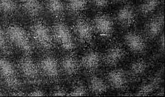
Figure 4. Wide 1 subscene (15 km x 15 km; 28m resolution) of the Persian Gulf acquired February 18, 1998. The bright targets are ships and oil rights. Oil slicks (dark curvilinear features), advected by prevailing currents and winds, are clearly visible. RADARSAT date © Canadian space Agency/Agence spatiale canadienne 1998.
3.0 Summary
With increased pressure toward sustainable development of the coastal zone, RADARSAT data provides valuable information for operational resource and environmental monitoring. For regions were perennial clouds exist, the virtually weather independent, day/night imaging capabilities of RADARSAT will provide a new level of information, and represents a new tool for coastal zone monitoring. A number of coastal monitoring applications are enhanced by varying the SAR incidence angle, and RADARSAT's advantage relies on the ability to adjust the incidence angle to suit a particular application. From monitoring coastal development and detection of oil slicks to ship detection in the EEZ, RADARSAT offers considerable flexibility in terms of image resolution and spatial coverage area, thus permitting data acquisition optimized for a particular application. In addition, the planned five-metre resolution, multi-polarization capability for RADARSAT -2 will provide significantly better information for agencies charged with management of the world's coastal zones.
Reference
- Freeberg, M,R. Wrigley, K. Dunlop, D.Sullivan, and G. Staples, application of Sapce-Based Radar Systems to Fisheries Monitoring, Control, and Surveillance, in proceedings, Third thematic Conference on Remote Sensing for Marine and coastal Environments, Seattle, WA September, 1995.
- Oil spill Intelligence Report (OSIR). Volume XX No.2 - 9 January 1997; Volume XX No. 3 -1 6 January 1997; volume XX No. 4 -23 january 1997, volume XX No. 5 -30 January 1997; volume XX No. 6-6 February 1997.
- Raney, R. Keith, A. Luscombe, E. Langham, and S. Ahmed, "RADARSAT", In Proceedings of the IEEE, Vol. 79, No. 6, June, 1991.
- Staples, G.C., J. Hurely, L. Safarian, and R.S. Burns, RADARSAT-1 Emergency Response for Oil Spill Monitoring, Proceeding Fifth International Conference on Remote Sensing for Marine and Coastal Environments, San Diego, CA, October 1998.
- Staples, G.C., W. Stevens, B. Jefferies, and D. Nazarenko, Ship Detection using RADARSAT SAR Imagery, in Proceedings Geomatics in the Era of RADARSAT, Ottawa, Canada, May 1997.
- Vachon, P.W., J.W. Campbell, C. Bjerklund, F. Dobson, and M. Rey, Ship Detection by RADARSAT SAR: Validation ad Detection Model Predictions, Can J. of Rem. Sens., Vol. 23, No. 1, March 1997.