| GISdevelopment.net ---> AARS ---> ACRS 1997 ---> Poster Session 1 |
Lower Tropospheric Aerosol
Profile Obsevation by Ground -Based Lidar at Kmitl, Thailand (130 N,
1000e)
Somkiat Lerkvarnyu, Kobchai
Dejhan, Fusak Cheevasuvit, Paibon Tooprakai
Faculty of Engineering
King Mongkut's Institute of Technology Ladkrabang, Ladkrabang,
Bangkok 10520, Thailand.
Tel : 66-2-3269967 , 66-2-3269081, Fax: 66-2-3269386
E-mail :kibachai@telelan.telecom.eng.kmitl.ac.th
Ekachai Prommas
Faculty of engineering
Kasem Bundit Untiversity, pattanakarn Road,
Bangkok 10520, Thailand.
Abstract Faculty of Engineering
King Mongkut's Institute of Technology Ladkrabang, Ladkrabang,
Bangkok 10520, Thailand.
Tel : 66-2-3269967 , 66-2-3269081, Fax: 66-2-3269386
E-mail :kibachai@telelan.telecom.eng.kmitl.ac.th
Ekachai Prommas
Faculty of engineering
Kasem Bundit Untiversity, pattanakarn Road,
Bangkok 10520, Thailand.
Troposhperic aerosols effects on climate in directly through various cloud formation while direct through sun night attenuation. Depending on a location, the aerosol come form various source that show variation in both time and space. In Thailand, (130 N, 1000E) the first laser remote sensing or LIDAR system was installed at the king Mongkut's Institute of Technology Ladkrabang ( KMITL) to study the aerosol profile in vertical axis. Principally, the lidar system consists of laser source (Nd :YAG ), 28 cm Schmnidt-Cassegrain telescope, photo multiplier tube (PMT) and data acquisition system.
Introduction
After the laser device invention, the various lasers were applied to used on many field, and in the field of work for detecting the target which well know as radar or remote sensing. Ion this field, the laser have been palled to form in several behaviors such as space borne , or ground-based radar. The laser have been used to study the composition of many particles mixing in the atmosphere including to study the pollution which was made by human activity. A system is used to study complex particles in the atmosphere is called laser radar, optical remote sensing or LIDAE ( light detection ad ranging ) and in this report will call lidar. Currently, it has many type of lidar system depending on the purpose of measurements, such as the measurement of ozone, vapor water, sodium and etc., including the aerosol measurement in boundary layer. Each behavior of measurement must be specific techniques. Moreover, for arbitrary propose the lidar system cab be installed on airplane, satellite, or ground . in tis report, the first ground-based Mie lidar system was established at KMITL, Thailand. The Mie lidar techniques concern the light scattering as elastic scattering, nd lidar system will measure in vertical axis about 9 km height to find the aerosol profile in the form of scattering ratio. The aerosol in boundary layer occur from various sources, including the human activity. Therefore, if the regarded place or time is distinct, the aerosol profile will be not the same. The scattering ration of aerosol profile can be obtained form the backscattering of laser light that mainly separate in two causes. On e is the laser light scattering only form the molecule of was which usually call the Rayiegh scattering and second is the scattered light occurring from dust, aerosol, and the whole particles in the laser beam. Concerning the size of aerosol when compared with the laser wavelength, the size of aerosol are larger than the laser wavelength, at this reason the scattering will be call Mie scattering. So that, the ration between the signal which scattered form all particles and the scattering signal from molecule is much more than one in the altitude that the aerosol occurs.
Lidar equation
In the experiment, the system is monostatic lidar that means the tr4ansmitter and receiver is located in the same place. Normally, in the lidar equation, the received signals are inversely proportional with square of distance, and the laser energy will be transmitted in vertical axis that mean the received signal depend on altitude . the Mie lidar equation can express as follows.
Where K: lidar constant, T: atmospheric transmittance, Z: distance.
In equation (1) the Bm is the backscattering cross section of aerosol and Br is the Rayliegh backscattering cross section . normally, Br is larger than Br and both altitudes have same parameter. Generally, the data analysis is suitable form in the backscattering ration of Mie and Raykiegh backscattering cross section. It expresses as;
In equation (2), if any region in the laser beam which disappear aerosols, the Bm approaches to zero so that the scattering ration is always equal to one. O the country, the scattering ratio is more than one, if aerosol occur in concerning region.
The configuration of lidar system is sown in figure 1. Transmitter, the Nd:YAG laser emitters the second harmonic wavelength (532 nm) and the laser beam is expanded, approximately 4 cm diameter, by beam expander. The laser beam is transmitted in the vertical axis with respect to the earth. Receiver, the telescope with 30 cm diameter will collect the scattered laser light that scatter form molecule and any particle in the field of view of receiving telescope. The collected light by telescope will focus on a photomoultiplier which convert energy to electrical signal . and, the return signal will be changed from analog to digital (A/D) by LeCroy 9310. one recorded signal is the total average of 500 repetition. Finally, the digital signal will be transferred to a personal computer where the signal will be processed and analyzed via parallel port. The detailed system is shown in table 1.
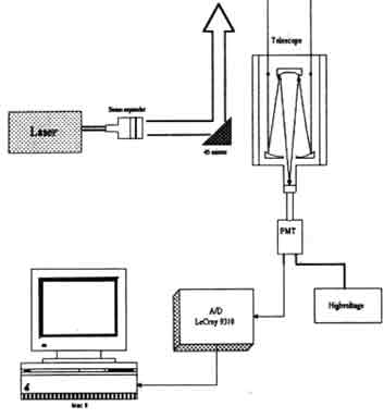
Figure 1. System Configuration
|
| |
| Transmitter; | |
| Laser | Nd:YAG, SHG(532 nm) |
| Output | 180 mJ/p |
| Repetition | 10 Hz |
| Beam div. | 0.1 mrad |
| Receiver : | |
| Telescope | sehmidt-cassegrain 28 cm diamter |
| Detector | PMT,S-1 R3236 Hamamatsu |
|
| |
Experimental results
Having observed, the return as shown in figure 2, the photo from oscilloscope at the output of photo multiplier tub e, and the signal power are rapidly decreasing when the distance is increased moreover, the peak of return signal means that the altitude, about 300 m, of the over lap between laser beam and field of view of receiving telescope. The 500 signal is accomplished and analyzed to obtain the backscattering cross section 1 as shown in figure 2.
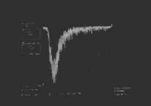
Figure 2. Photo from oscilloscope
Figure 3 shows the relation between the back cross section in log scale with altitude while the dot line represents the Rayliegh backscattering cross section and the thick line is the backscattering cross section which obtain from data. The backscattering ratio in equation (2) can be obtained as shown in figure 4. therefore, if the aerosol appears at any altitude, the scattering ration will increase and if the observations are continuously, the scattering ratio profile in vertical axis will be obtained as shown in figure 5. these profiles show the located aerosol which vary with time and space.
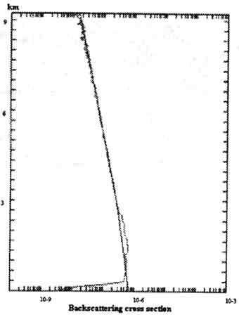
Figure 3. Backscattering cross section
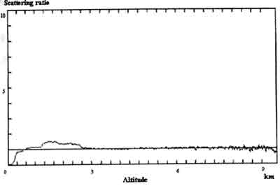
Figure 4. Scattering ratio
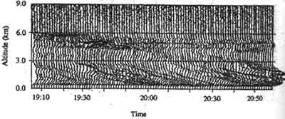
Figure 5. Aerosol profile
Summary
The first study and experiment of Mie lidar system to obtain the aerosol profile based on scattering ratio between Rayliegh backscattering and Mie backscattering can be done. However, ratio assume that the composition of particles in atmosphere consists only of molecules and aerosol. The practice, it is not true, its is not true, it has many particle in the boundary layer. In the future, it is a need to develop the lidar system in another techniques with higher layer.
References :
- J.D.Klett, J.Appl. Out., Vol. 20, No, pp 211, 1981.
- R.M. Measures , Laser Remote Sensing: Fundamentals and Application, New York, NY: Wiley, 1984.
- F.G.Fernald, J.Appl. opt., Vol .23, No5, pp. 652-653, 1984.
- F.G.Fernald, B.M. Herman, and J.A. Reagan, J.appl. Meteoro., vol 11, pp. 482-489, 1972.
- B.R.Clemesha, G.S.Kent, and R.W.H.Wright, J.Appl. Meteoro., vol. 6, pp. 386-395, 1967.
- K.Parameswaran, K.O.Rose, and B.V.Krishna Murthy, J.appl.Opt., vol 30, no21, pp. 3059-3071, 1991.