| GISdevelopment.net ---> AARS ---> ACRS 1997 ---> Coastal Zone/Oceanography/Meteorology |
Somkiat Lerkv Aranyu*, Kobchai Dejhan*, Fusak Cheevasuvit*, Paiboon Tooprakai*, Somnuk Yartpramote**, Buntoon Phithakwong**
*Faculty of Engineering King Mongkut's Institute of Technology Ladkrabang*Bangkok 10520, Thialand.
Tel: 66-2-3269976, 66-2-3269081, Fax: 66-2-3269086
Email: kobchai@telecom.eng.kmitl.ac.th
**Faculty of Engineering, Saint John's University
Ladprao, Bangkok, 10900, Thialand.
Abstract
This paper presents the applications with experimental results of laser for Remote Sensing to measure the height and thickness of cirrus cloud. The particle in atmosphere will be measured by using the second harmonics of Nd: YAG laser (532 nm). The laser source will be installed in vertical axis with respect to the earth, the telescope will be used to receive the scattered wave of laser in the sky. The photomultiplier tube (PMT) amplifies the received signal in the form of two polarizations. The amplitude and phase of photon counting signal with 300 m resolution from cirrus cloud will be processed and analyzed by the PC. The experimental results show that the height of cirrus cloud is about 15 km from the earth and its thickness is about 4-6 km.
Introduction
It is obviously that the earth is covered by various gases which was divided to several layers with respect to the characteristics of the atmospheric temperature. The lowest atmosphere is called troposphere or boundary layer in which has many phenomenon such as raining snow, cloud or fog. Moreover, the characteristics of such phenomenon are different in each country or different position of the world. Each country or each position of the world has special altitude of troposphere. Therefore, in different place, the altitude of boundary layer is not the same. If the position refers to the latitude line, the height of troposphere varies in each line. On the other hand, if it refers to the longitude line it is small distinct. Generally, the area in Europe or Japan will have the troposhperic altitude about 7-8 km while these areas are located around equator and it is about 17-20 km. The condensed cloud, from vapor at any altitude, in boundary layer can be divided in several types with respect to the altitude. Once is cirrus cloud which located at the top of troposphere or between connection of troposphere and stratosphere layer. Normally, the characteristics of cirrus cloud is ice crystal, and the connected region which contain the cirrus will be called the tropopause. Ideally, the temperature is constant through the tropospause region and changes directional with the temperature gradient during passing through stratosphere layer, in practically the temperature between tropopause layer has a small change with altitude. Considering the behavior of the light propagation, if the linear polarization light is propagated through crystal media, the polarization of scattered light must be changed. It causes to have the higher depolarization. On the contrary, the linear polarization propagate via the media which containing the particles with spherical shape, the polarization must be zero. Therefore, the laser linear polarization light is propagated into the atmosphere, the depolarization ratio has various values depending on the kind of particles in laser beam.
Theory
The receiver receives the scattered light in according to the transmitted laser light the field of view of receiving telescope. Thus, the radar equation will be used. The energy depends on the square of distance for the time is converted. If the transmitter and receiver of the radar or any Remote Sensing system was located in the same place, it will be called the monostatic radar system. Meanwhile, the bistatic radar system is a separated place of the transmitter and receiver station. The ground-based monostatic radar will be used in this experiment. Consequently, in the optical Remote Sensing the photon counting techniques is helpful when the return signal is very weak. The optical Remote Sensing equation is as follows:
N(z)=(hT2)( P l i /hc)(b(z)n(z)DZ)(Ar/4pZ2)+Nnt (1)
Where
N(z)=expected number of photons detected in the interval DZ
n(z)=particles density at range Z
Nn=expected photon count per range bin per pulse due to background noise
b(z)=effective particles backscatter cross section
DZ=receiver range bin length
Ar=receiving telescope aperture area
l=optical wavelength
h=Plank's constant
c=light velocity
P=laser power
T=one way-transmittance of the lower atmosphere
R=laser pulse rate
t=integration time
h=system efficiency
The depolarization is defined as
d=b^/b½½ (2)
Where b^=orthogonal polarized component
b½½=normal polarized component
Normally, the scattered light from spherical shape has no effect with the polarization. The total particles in atmosphere is completely spherical shape, the depolarization should be zero. It has really various shapes of particles in the atmosphere, especially in the boundary layer.
System
The ground-based optical Remote Sensing is established in this experiment. The green light of the second harmonic wavelength (532 nm) of Nd: YAG laser is the transmitter. The laser light will be transmitted in the perpendicular direction with respect to the earth as shown in Figure 1.
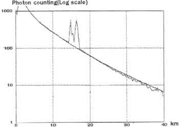
Figure 1 System configuration
In Figure 1, the laser light from the source propagates toward into a beam expander which the laser beam to 4 cm, approximately. Finally, the laser light will be transmitted in vertical axis by using 450mirror. The telescope is carsegian type with 28 cm diameter as the receiver and located near the 450mirror, as shown in Figure 1. The scattered light is collected by telescope and pass to beam splitter for separating the orthogonal and normal component before focusing on a photomultiplier tube. The electrical signals of both component from light energy. After the signal is amplified and discriminated, the multichannel with 300 m resolution that interface to personal computer will count the photon pulse in each bin. The detailed system is shown in Table 1.
| Transmitter | ||
| Laser | Nd:YAG, SHG (532 nm) | |
| Output | 180 mJ/p | |
| Repetition | 10Hz | |
| Beam div. | 0.1 mrad | |
| Receiver: | ||
| Telescope | Schmidt-Cassegrain 28 cm diameter | |
| Detector | PMT,S-1 R3236 Hamamatsu | |
Experiment results
In experiment,
after the over of the laser beam and the view of telescope occurs, the
return signal appears and the multichannel will count photo pulse in each
interval. One recorded signal is the total of 3000 pulse repetition, and
obtained data as shown in Fig 2.
Figure 2. Photon counting
data.
Figure 2 shows the signal peak corresponding to initial
of beam over lap, so that the return signal, scattering from all particle
in atmosphere including cirrus cloud decrease as the distance increases.
After separating the return signal which come from particles and noise,
the result is shown in Figure 3.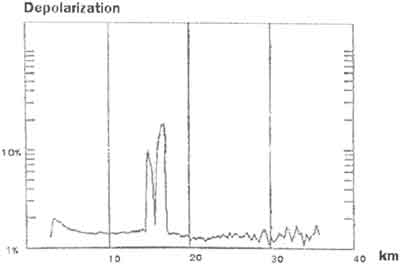
Figure 3. Scattering
ratio.
Figure 4. Depolarization.
In Figure 3 shows
the scattering ratio that occurred from all particles expected from
molecules in atmosphere. Figure 4 shows a result of depolarization ratio.
The first and end echo signal with higher depolarization, which come from
cirrus cloud. In Figure 4, it is about 15-17 km. Finally the continuous
collected data is shown in Figure 5 that the occurring cirrus cloud show
the variation for both time and space.
Figure 5. Cirrus and cloud
profile.
Summary
In this experiment uses the
ground-based optical Remote Sensing to find the altitude of cirrus cloud.
The observation, however, can make when the atmosphere is clearly. In
addition, the results of altitude of cirrus cloud in troposphere layer at
KMITL, Thialand (130N, 1000E), which located nearly equator is about 15 km
and varies with time and space. The occurring cirrus cloud is located at
the top of troposphere corresponding with the height of troposphere in
equator region for the altitude is about 17-20
km.
References