| GISdevelopment.net ---> AARS ---> ACRS 1995 ---> Poster Session 4 |
Development of a Stereoscopic
Image Processing Software
Nobuhiko Mori
Earth Remote Sensing Data Analysis Center (ERSDAC)
Forefront Tower, 3-12-1, Kachidoki, Chou-ku, Tokyo 104, Japan
Abstract
Earth Remote Sensing Data Analysis Center (ERSDAC)
Forefront Tower, 3-12-1, Kachidoki, Chou-ku, Tokyo 104, Japan
A digital stereoscopic image processing software has been developed on a personal computer (PC) system. The system was originally developed as a digital photogrametric system, and had a special three dimensional (3d) display module which could display stereoscopic drawings together with stereoscopic images. The stereoscopic drawings were used as a tool of man-machine interface. For instance, stereoscopic points on stereoscopic images were used to inform the positions of some stereo conjugate points to computer, and to correct the results of computer stereo matching. The functions of the stereoscopic image processing software which have been developed on this system are mostly similar to those of an ordinary two dimensional image processing software. Using the software, images can be processed, overlaid and changed into stereoscopic images. Further more, this stereoscopic graphics can be used as a tool of man-machine interface. This ability has been taken over from the digital photogrametric system. Thus software can be used widely where geographical information is necessary. As an application example, stereoscopic images which can be used in earth resource exploration field have been made using this software and presented here.
1. Introduction
Topographic information is very important in many application fields, such as earth resource exploration, route selection (road, pipeline, etc.), dam construction and wide area development. However, it is very hard to get topographic information on digital systems because usually they have only two dimensional display. some digital photogrametric system have 3D display, but no sufficient image processing software attached. In this work, a stereoscopic image processing software has been developed on a PC system with 3D display. This system was originally developed as a digital photogrametric system, but now the ability of a digital stereoscopic image processing system is developed.
This system has a special 3D display module, which has an ability to display stereoscopic drawings together with stereoscopic images. Figure 1 shows the function of the 3D display module. In figure 1, stereoscopic drawings are memorized in Video Random Access Memories (VRAM), and stereoscopic images are in Frame Memories. Left image and drawing, and right image and drawing are overlaid respectively and displayed on a display one by one alternately. Observer can get a stereoscopic view by using liquid crystal shutter glasses, which are synchronized with the display. By using this module, this system get a special ability as man-machine interface.
Figure 1 The function of the 3D display module
2. Man-machine interface in DEM extraction from digital stereoscopic images
Generally speaking, image recognition is very difficult for a computer because there are too many informations in images to be analysed. It is also true in the case of stereo matching, which is one technique to determine stereo conjugate points automatically with digital photogrametric systems. Now the errors of stereo matching are very serious problem for automatical DEM extraction, because it is impossible to get rid of them completely by present computer techniques. Many methods are already proposed, but they all need to be improved. It seems that the best way is to get human help at appropriate stages. In order to get human help, man-machine interface (3D display module) is necessary. In automatical stereo matching, man-machine interface can be used to reduce matching errors at two stages, before and after the stereo matching.
Before the stereo matching, some stereo conjugate points can be informed to a computer by using the man-machine interface. Photo 1 is one example. In this case, 25 stereo conjugate points were informed to the computer, which were determined manually by using 3D display module. Because this module can display stereoscopic images together with stereoscopic drawings of points, the hight of the points can be easily adjusted to the hight of earth surface of images by using a mouse device.
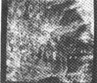
Photo 1 Manually determined stereo conjugate points
Photo 2 is another example. In this case, stereo conjugate lines were informed to the computer. These lines were drawn one by one along the earth surface of images with a mouse looking at the 3D image through liquid crystal shutter glasses. The sequence to draw these lines are as follows.

Photo 2 Manually drawn stereopair lines
- First draw one line of stereo pair along a valley or a ridge in one (left or right) image.
- Next draw the second line just on the line mentioned above in the other image.
- Repeat these two kinds of drawings.
After the stereo matching, the errors of automatically determined stereo conjugate points can be corrected by using the man-machine interface. Photo 3 is a simultaneous display of stereo-scopic images and stereo conjugate points determined automatically. When observed through liquid crystal shutter glasses, correct points are positioned on the surface of a model of a mountain and error points are positioned in the air or under the ground. These error points can be corrected by the mouse easily. In the photo, a pair of big cross marks indicate the points under correcting.
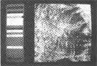
Photo 3 : Simultanious display of stereoscopic images and stereo conjugate points.
3. Development of a general purpose stereoscopic image processing software.
A stereoscopic image processing system is very useful in such field that needs topographic information, especially when it has man-machine interface function mentioned above. Since there are now scarcely any stereoscopic image processing systems which have these abilities, it has been planed to develop such a system. Because there was a digital photogrametric system which was already developed using a general purpose stereoscopic image processing programs on this system. The programs were developed on the OS of the personal computer, MS-DOS. The functions of the programs developed on this system were as follows: enlargement and reduction, brightness enhancement, affin transformation, calculation between images, cutting out and displaying a part of a big image, etc. A program which produce stereoscopic images from a digital orthoimage using DEM is also developed.
Photo 4 and 5 show the example of enlargement. Photo 4 is an alternative display of stereo-scopic images, and the operator can get a stereoscopic view through liquid crystal shutter glasses.
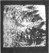
Photo 4 Selection of the place to enlarge by a square
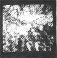
Photo 5 Enlarged image of te selected place
A square in the photo, the size of which is determined from the rate of enlargement, is overlayed on one of the stereoscopic images. The operator can move the square in the stereo-scopic view with a mouse, and can select the place to enlarge. Photo 5 in the enlarged image of the place selected in photo 4, and the operator also can get a stereospopic view by looking at the images in photo 5.
A 3D graphic program, which can draw stereoscopic points, lines, circles, etc., has also been developed to serve a tool of man-machine interface to the system using the two dimensional graphic programs provided in the OS, MS-DOS. Photo 1 is an example of writing stereoscopic points on stereoscopic images. Photo 2 is another example of writing stereoscopic lines on stereoscopic images. In this case, stereopair lines are written one by one. Photo 6 is another example of drawing stereoscopic lines. In this case, stereopair lines can be written at one time, but the hight of the line in the 3D image can not be changed. This mode can be used to draw contour lines.

Photo 6 Drawing stereopair lines at one time
4. An example of the utilization of stereoscopic image processing
This stereoscopic image processing software can be used in many fields, such as earth resource exploration, route selection, dam construction, wide area development, etc., The experiments of the utilization of this software have already been done in some fields. Photo 7 is an application example in the field of earth resource exploration. In the photo 7, broken lines are faults, filled dots are hot springs and small marks like eyes are veins. These informations were written of a orthoimage using the calculation program developed in this system, and then transformed to stereoscopic images. The B/H ratio of these stereoscopic images is 0.5, which is the most suitable value in this case. Looking at these stereoscopic images with liquid crystal shutter glasses, observers can t=get a precise topographic information together with images and other important informations, can draw dots and lines on these stereoscopic images to indicate the results of image analysis.
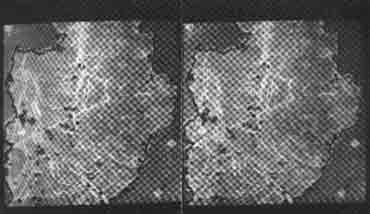
Photo 7 An example of stereoscopic image processing
5. Conclusion
A stereoscopic image processing software has been developed on a PC system which was originally developed as a digital photogrametric system. The system has a special 3D display module which has an ability to display stereoscopic drawings together with stereoscopic images.
Besides usual image processing programs, the functions of which are similar to ordinary ones in a two dimensional image processing system, a 3D graphic program has also been developed. The latter one can be used to draw stereoscopic points, lines, etc., on stereoscopic images. By using this system, many informations about stereoscopic images can be informed from operator to computer. This system has a powerful man-machine interface ability. The usefulness of this ability has been explained in paper in the field of digital photogrametry and earth resource exploration. This system has high application potential in many fields.
Finally I would like to express my appreciation to the members of Murai laboratory in Tokyo university and NEC corporation for their contributions to this research.
Reference
- M. Boulianne, P.A. Gagnon. J.P. Agnard, C. Nolette; Large Scale Map Revision Using a PC-Based Videoplotter; Issprs Com. 4, Tsuduba, May, 1990,pp. 273-279.
- N.Mori, S.Murai, X.Bai; Development of a New Method Attaching precise Topographic Information to Gis by Using 3D Display; ACRS, China, Nov., 1990.pp.H.2.41-H24.6
- N.Mori, T. Tagawa, S.Murai, S.Ito;DTM Extraction and Its Application Using a Digital Stereo-scopic Image Processing System with 3D Display; ACRS, Singapore, Nov., 1991, pp.p.8.1-p.8.6 4.N.Mori, S.Masuda, S.Murai; Development of a PC-Basd Digital Photogrametric System; ISPRS, Washington, Aug., 1992B2-2,pp. 319-322.