| GISdevelopment.net ---> AARS ---> ACRS 1995 ---> Poster Session 4 |
Effect of Atmospheric
Correction on Satellite Image Data by Lowtran Model
Kiyoshi Toril*, tomoyuki
Mase** and Takashi Hoshi***
*Dept. of Agric. Eng. Kyoto univ, Kyoto, Japan
** Ministry of Agric., Forestry & Fisheries, Tokyo, Japan
***Dept. of Comp. & Information Sci . Ibaragi Univ, Hitachi, Japan
Fax (Int'l+81)+773-64-3617,
E-Mail cxk02755@niftyserve.or.jp
Abstract *Dept. of Agric. Eng. Kyoto univ, Kyoto, Japan
** Ministry of Agric., Forestry & Fisheries, Tokyo, Japan
***Dept. of Comp. & Information Sci . Ibaragi Univ, Hitachi, Japan
Fax (Int'l+81)+773-64-3617,
E-Mail cxk02755@niftyserve.or.jp
Remote sensing technique is one of the most expected tools to be used in environmental measurements. However, distortions and noises contained in satellite images become serious impediments for quantitative analysis.
In the present study, we used Lowtran Model to eliminate atmospheric effects with respect to thermal infrared, visible and near infrared bands due to technical differences and examined the result. Data used in the study are Landsat 5 TM data on Chaophraya plain, Thailand, and Kojima bay Okayama Pref., Japan We obtained interesting data derived from the difference in atmosphere in the tropics and temperate zone.
1. Introduction
Accuracy in earth survey by satellites has been raised with the advancement in space technology and measurement techniques and objects of the survey have also been variegated, Observations of vegetation, soil water, and chlorophyll content and earth surface temperature are included in the related fields. With the progress, progress, programs for satellite data analysis has also been developed and excellent soft wears such as arc/info, IDRISI and ERDAS have become popular. Analytical method has shifted from visual and qualitative ones at the beginning to quantitative one noises and they form a great hindrance on quantitative analysis. These errors and noises are roughly classified into 3 categories; noises derived from ability of a sensor, geometrical distortions, and atmospheric effects. Here, we discuss about elimination of atmospheric effects, which is the main theme of correction.
Presented at the 16th Asian Conference on Remote Sensing, Surananree University of Technology, Nakhon Ratchasima, Thailand, November 20-24, 1995.
2. Concepts of Atmospheric Correction
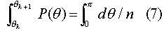
Radiation entering a sensor is classified as in Fig. 1. Atmospheric correction is the processing to eliminate S2 and S4 leaving S1 and S2 which are the objects of observation as well as to eliminates S5 in Fig. 2 contaminating from the vicinities of the observed pixels. However, techniques for atmospheric correction have not been established and many studies are still going on at present. A general formula for transmission of radiation in a multiple atmospheric model is as follows,
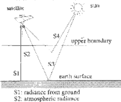
Figure 1 Incxident radiation to satellite senser
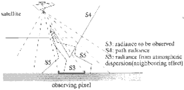
Figure 2 In the case of visible, and near-infrared band
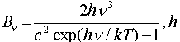
where Iv: spectral radiance in frequency range v, v::optical thickness, m: cosine of the zenith angle, f: azimuth, : eearth : emission rate of the ground, eair emission rate of the medium, Bn: Planck function,
 Planck constant, n:
frequency, c: velocity of light, k: Boltzmann constant, temperature of the
medium, temperature of the ground, av: albedo of the primary scattering of
the medium, and Pn: probability function of the scattering angle. The left
hand side of the equation is the radiance observed by a satellite the
first term of the right hand side is the surface radiation, the second
term is the atmospheric radiation and the third term is the scattered
light including that by the earth surface. Optical thickness, , is the
integrate of the volumetric dispersion coefficient, Kv, from
the upper boundary of the atmosphere (z=µ) to the
altitude z and is defined as follows,
Planck constant, n:
frequency, c: velocity of light, k: Boltzmann constant, temperature of the
medium, temperature of the ground, av: albedo of the primary scattering of
the medium, and Pn: probability function of the scattering angle. The left
hand side of the equation is the radiance observed by a satellite the
first term of the right hand side is the surface radiation, the second
term is the atmospheric radiation and the third term is the scattered
light including that by the earth surface. Optical thickness, , is the
integrate of the volumetric dispersion coefficient, Kv, from
the upper boundary of the atmosphere (z=µ) to the
altitude z and is defined as follows, 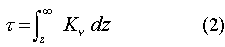
To solve the equation (1), parameters including atmospheric temperature and optical thickness (scattering coefficient) are needed. Formerly, these parameters were decided on the basis of the actual measurement values obtained from a radiosonde in the vicinity of the site of analysis or correlation in observation intensities in multiple bands. However, in recent years, excellent atmospheric models such as LOWTRAN and FASCODE have been published facilitating easy access to these parameters. In the present study, we used LOWTRAN 7 as an atmospheric model in our calculation. LOWTRAN 7 is a program source written in FORTRAN and, in a simple case, it can provide optical thickness, atmospheric temperature and altitude distribution of aerosol content in each model selected from Table 1.
| Parameters related to temperature, humidity, gaseous concentration | Parameters related to aerosol | ||
| Tropical Type | No aerosol | Summer type | Stratospheric type |
| Midlatitude summer type | Rural type (23k km visual range) | Winter type | Aged volcanic type |
| Midlatitude winter type | Rural type (5km visual range) | Fresh volcanic type | |
| Subarctic summer type | Marine type | ||
| Subarctic winter type | Urban type | ||
| 1976 U.S. type | Tropospheric type | ||
| User definition | Fog type | ||
| Desert type | |||
| User definition | |||
The image data used in the present study is the one observed by LANDSAT-Thematic Mapper (TM) and it has 7 bands ranging from visual to thermal infrared wavelengths (0.45.12.5mm). The parameters used in Equation (1) differ greatly depending on the wavelength and the method of atmospheric correction differs accordingly. In the present study, we discuss about atmospheric corrections in 2 wavelength zones, visual and near infrared zone and thermal infrared zones.
2.1 Data correction in thermal infrared zone
LANDSAT-TM consists of 7 channels and only one channel is designated to the thermal infrared zone(10.4mm-12.5mm). Calculation for correction of thermal infrared band data concerns with accurate calculation of the earth surface temperature. While the model equations to convert the observed values to the surface temperature have been published by NASA,etc. they are either uniform totally ignoring longitude and atmospheric effects of the observation site of localized concerning specific data. So in the present study, we modified the correction technique to be applicable to all sorts of atmosphere or earth surface can be ignored and, therefore, radiation laws can be simplified greatly. In other words, upward radiance, Iobs from the earth surface to the satellite is expressed by the following equation obtained by multiplying each term of Equation (1) by the satellite response function Rn, and integration it by the instantaneous angle of view and frequency. (3)

In the equation u1u2 the range of instantaneous field of view and v1 v2 : the range of frequencies observed by the satellite. In the calculation, atmosphere up to 100-km altitude was horizontally divided into 32 uniform layers and the atmospheric up to 100-km altitude was horizontally divided in to 32 uniform layers and the atmospheric temperature and optical thickness determined by LAWTRAN 7 as well as the response function of the sensor were substituted into Equation (3). Then. was changed in the temperature range corresponding to the atmospheric model and the observed radiance, Iabs was determined .While LOWTRON presents a mean data of a long period including fine and rainy weather, observation by the thermal infrared remote sensing is limited to fine weather and therefore, humidity which is an important factor in the present problem becomes excessive in comparison to that of the atmosphere at the time of observation. Because of this, only humidity was modified to the respective winter types in the mid latitude and subarctic summer models in the present study, The maximum input radiance of the sensor was set as Imax =Bv (340) and the minimum input radiance as Imin =Bv (200) and the digital output value, D, is recorded as follows.
By the above equation the supplied satellite data, D, and the ground temperature, Tearth are correlated as follows, Here, aerosol models were all designated to the rural model (5 km visual range).
Figure 3 Correlation between quantitized radiance and surface temperature
The ratio of atmospheric radiation included in the observed radiance, Iabs becomes as Fig. 4 The temperature of the observed radiance, Tabs of Fig. 4 is defined by Bn (Tabs)=Iabs
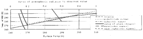
Figure 4 The ratio of atmospheric radiance to observed value
2.2 Correction of visible and near infrared data.
In LANDSAT-TM, 4 channels are designated to the visual range and 2 channels to the infrared range. In these wavelength ranges, Planck function is negligible and, therefore, B n (T) =0, we only have to consider the third term of the right hand side of Equation (1)As in Fig. 2, dispersed light and reflected light are dealt with as the light entrance paths. It is necessary to eliminate S4 and S5 to extract the objective S3 .S4 is considered as being constant in the horizontal direction bur S5 increases as it approaches to the observation pixel. If the point (X,Y) of the ground coordinates is observed, introduction of a filter a (X,Y) gives the observed radiance, Iabs,

assuming that S5 is dependent only on the distance from the observation pixel and Iabs can be expressed as a sum of the convolution of S3 by the filter a (X,Y) and S4. As Path radiance, S4 is calculable by LOWTRAN, reflection intensity at the ground site (X,Y), Iearth (X,Y), can be extracted by reverse conversion regarding the filter a(x,y) as a point spread function provided that it is known. In the present study, a(x,y) was determined by the simulation wherein numerous photons were allowed to enter into the atmospheric models. The ground surface was regarded as Lambertian surface and the reflection flux as constant.
Essentially, we should let photons enter from far up in the atmosphere and count those entering the focusing surface of the sensor through dispersion and reflection but it is difficult to let a sufficient number of photons enter the focusing surface of a few mm2 of the area present at 700 km altitude above the ground. Thus, we let the photons enter a random point within the observation pixel on the upper boundary of the atmosphere from the satellite and determined the number of photons arriving at the ground (X,Y) to decide the filter a (x,y).
Free journey, L, is the distance to the point where a photon collides with next particle and is defined by the following equation using the uniform-distribution random numbers from 0 to 1, ran(a)
As for scattering angle, qran(a) was generated after a number , n (n=200, in the present study), of qk , satisfying the following equation were prepared using the probability function P(q) for the scattering angle. q
Then, qk satisfying the following equation was adopted.
The azimuth of scattering, f was set 2pran assuming isotropy. P(q) differs greatly depending on whether the collided particle is air molecule or aerosol. It follows Rayleigh's scattering law if the photon collides with a fine air molecule.
but it follows Mie scattering if collision with a larger aerosol takes place. We used built-in P(q) in LOWTRAN related to individual aerosols for calculation. Whether the collided particle was and air molecule or aerosol was judged by generating ran(a) (using the ratio between the dissipation coefficient due to air molecular scattering within the layer and that due to aerosol scattering Convergence of the solution was decided by diving the earth surface into pixels and finding the convergence of the maximum value in the rate of change of the photons N(X,Y) reaching the cell (X,Y) Then, filter a(x,y) can be obtained according to the following equation,
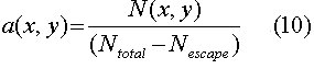
Fig. 5 and 6 show the examples of the filter a(x,y). The center of the mesh is the observation pixel, the cell division is 30X30 [m] on the basis of the satellite specificity and the value unit is %.
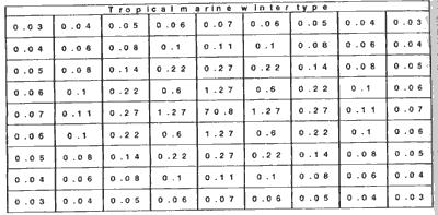
Figure 5 Point spread function (Bangkok)
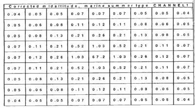
Figure 6 Point spread function (Okayama South)
3. Prospects
We attempted correction of satellite data using atmospheric models and found that it would be necessary to confirm accuracy of the atmospheric models themselves or to modify the problem of selecting atmospheric models. In the present study in which visual infrared data was corrected using an inverse filter, accuracy in the periphery of the data drops due to the assumption of periodicity of the data. As for the filter, it is strongly dependent on the scanning angle and its effect is detected in a sensor with an extremely small scanning angle such as LANDSAT-TM. Therefore, it is necessary to adopt a filter considering the scanning angle at a point distant from that right under the satellite. Modification of these points facilitates elimination of principal distortions and noises included in the satellite data. Reliability of the analytical result is expected to improve greatly through this correction even though the analytical process thereafter is left to the commercial software.
4. Concluding remark
In the present study, we applied LOWTRAN model to satellite image data which was divided into thermal images and visual infrared images. In the thermal images, the values did not differ much from those predicted from the conventional NASA model in the mid latitude region including Japan but a rise of about 5*C was predicted in the tropics. Although it is difficult to give a conclusive judgment as we have not conducted the ground survey, application of the NASA model to the tropics seems to require careful consideration.
In the visual infrared region, we could introduce filters corresponding to the respective hands as shown in Figs. 5 and 6. A considerable amount of calculation is needed to apply these filters to enormous image data and carry out analysis and we are in the stage of examining how to introduce routine program. Thus, although we have not assessed the program with numerical ground, it seems to be modified greatly on the basis of visual judgment, especially in the regions including water zone.
The original code of LOWTRAN 7 was supplied directly from GPOS/L.W.Abreu, U.S. Department of the Air force, Simulation Branch, Optical Environment Division, Phillips Laboratory (AFSC) as a medium of MT. The majority of calculations in the present study were conducted under the development project of Kyoto University Center, Landsat 5 TM data was provided by NASDA (National Space Development Agency of Japan) and NRCT (National Research Council of Thailand) at special prices. We express our thanks to whom it may concern.
5. References
- Kneizys, F.X., et.al: Atmospheric Transmittance/Radiance: computer code LOWTRANG AFGL-TR-83-0187 (1983).
- Kneizys, F.X. et.al.: Users Guide to LOWTRAN7, AFGL-TR-88-0177, ERP, #1010 (1988).
- Tanba, S., et., al.; Proceedings of 2nd meeting of Earth Environment Monitoring from Space, Institute of Industrial Science, Univ. of Tokyo, 1994.
- Marchuk, G.I. et. al: The Monte Carlo Methods in Atmospheric Optics, Springer-Verlag, Berlin (1980).
- Markham, B.I. and Barker, J.L. Spectral Characterization of the LANDSAT Thematic Mapper sensors. NASA Conference Publication 2355, vol. II, Part I (1983).
- Takagi, M., et.al,: Image Analysis Handbook. Unversity of Tokyo Publication (1991).
- Japan Society of Photogrammetry and Remote Sensing : Techniques and practice of thermal infrared remote sensing. Kashima Publication (1985).