| GISdevelopment.net ---> AARS ---> ACRS 1995 ---> Plenary Session |
Mission Analysis for
Engineering Test satellite, Kitsat -3
Sungdong Park, Sungheon
Kim, Dan Kenu Sung, Soon Dal Choi
Satellite Technology Research Center (Sa TReC)
Korea Advanced Institute of Science and Technology (KAIST)
373-1 Kusung-dung, Yusung-Ku, Taejon, 305-7-1
Abstract Satellite Technology Research Center (Sa TReC)
Korea Advanced Institute of Science and Technology (KAIST)
373-1 Kusung-dung, Yusung-Ku, Taejon, 305-7-1
The SaTReC has developed and been operating two micro-satellites, KISAT-1 and 2, and is now developing the third satellite system, KITSAT-3 is designed and operated from the basis of engineering test purposes. The KISAT-3 system is a small satellite with a mass of approximately 100 Kg, however, 3-axis stabilized. Each subsystem has been designed from similar concept to the KIST-1/2, however system architecture is so unique and modular that can be easily modified and expanded for future missions.
This paper presents how the KISAT-3 system has been designed at system level. It will also include critical mission analyses such as power budget, mass budget, thermal analysis, link budget, operational scenarios and attitude maneuvering under given constraints. The results of mission analyses will generate a baseline system for preliminary design.
1. Introducting Of Kitsat-3 System
The Satellite Technology Research Center (SaTReC) has launched two of micro-satellites, KITSAT-1 and KITSAT-2, in 1992 and 1993, respectively. The KITSAT-1 was the first Korean satellite and has been developed as a collaborative project with University of Surrey in UK. The KITSAT-2 has been completely newly developed and test in Korea by Korean engineers with major changes on payloads and corresponding bus systems.
The SaTReC is now aiming to design, develop, and operate the third KITSAT using experience and well trained engineers obtained from KITSAT-1/2. The KITSAT-3 system will be SaTReC's unique small satellite and will be used as bus platform for SaTReC's future space missions. The primary mission objectives are development and in-orbit test of newly designed small satellite system especially demonstrating new techniques such as 3-axis stabilized attitude control system, solar panel deployment mechanism, common bus networked architecture, high resolution and multi-spectral camera system, and payload data transmission system in high data rate.
The mission payloads on board KITSAT-3 are a remote sensing payload with 15m resolution and pushbroom type CCD camera in three spectral bands, a space science payload with a high energy particle telescope and a radiation monitor which can measure radiation environment around mission orbit and can also distinguish what types of particles and in which levels, and a data collection payload collecting data measured from buoys floating on ocean.
The KITSAT-3 is supposed to be launch ready at the end of 1996 and designed to be launched by Chinese Long March IV as a secondary launch. The weight of KITSAT-3 system shall be less than 100 Kg and the dimension of satellite shall be within 45 x 45 x 60 (cm).
2. Mission Analyses
In order to configure the satellite systems, it is necessary to allocate performance to the satellite elements and to specify corresponding subsystems. The process to allocate performance and to evaluate them is generally called mission analysis. It required iterations and provides overall system configuration for preliminary design. It begins with analyzing the requirements and allocating performance parameters by establishing budgets for power, mass, and propellant. For KITSAT-3 system, the propellant budget is not considered, as there is not propellant system. The pudgeting must be based upon the mission orbit and operational view point. In this paper, power budget, mass budge, and initial thermal analysis will be mainly presented.
2.1. Orbital analysis
Prior to analyze requirements and allocate performance parameters, the Mission orbit should be defined clearly and analyzed first. The mission orbit would be one of the most important constraints to designs satellite systems. Once satellite system has been designed to be operated in a mission orbit. It needs significant modifications to be operated in others. Different orbital characteristics give different solutions for available power, battery's charge and discharge characteristics, and thermal control which is the most significantly affected.
The mission orbit of the KITSAT-3 is approximately 800 km of altitude and sun-synchronous orbit. The descending node will be about 10.30 AM , therefore the sum incident angel toward orbit ,it is assumed that the satellite is positioned at the initial position and the orbit properties are not significantly changed during mission life .
Sun-synchronous gives a lot of benefit to satellite system designer. It will give nearly contact sun illumination to satellite therefore available power and depth of discharge is constants at every mission orbit .Thermal environment is also moderate to adopt passive thermal control . For the remote sensing payload as the areas taken by camera system are illuminated at well contact level, it helps to control gain and integration time .
At 800 km altitude, the node spacings between successive orbits are calculated as 25.22 deg for a day ,6.92 deg for 4 days , and 2.46 deg for 16 days . as the field of view of KITSAT-3 camera system is 5 deg, the kitsat-3 can achieve completed coverage and take images at any area at lest every 16 days .If the attitude control system is well qualified , the revisit period can be reduced to 4 days with small attitude adjustment using reaction wheels.
Through the detailed analysis on orbit property , it can be calculated that the mission control center at the SaTReC has the contact time of approximately 48 minutes over 5 deg and 17 minutes over 20 deg per day .
2.2.Power Budget
The power budget is estimated by adding the payloads power requirements to power estimates for the spacecraft system . If the satellite system has several different requirements to power estimates for the spacecraft system . It is necessary to estimate power requirement separately for each operation mode , power requirement, it is necessary to estimate power requirement separately for each operation mode , paying particular attention to peak power need for each subsystem . Once defined power requirements and their duty cycle the required power from energy source can be calculated . from this result, we can size the solar panel and the battery capacities to supply enough power for operations and recharging batteries until the end of mission life . During this process the degradation on power subsystem over the mission life should be taken into account . radiation damages to the solar panels and depth of discharge and number of charge and discharge cycles of the battery are main factors for degradation .
| Subsystem | Estimated power (watt) | Duty cycle(%) |
| Spacecraft | ||
| Electrical power system | 20.0 | 100 |
| Attitude control system | 17.2 | †¹ |
| C&DH System | 2.5 | 100 |
| Transmitters/ Receivers | 10.0 | 100 |
| Structure/ Thermal | 0 | |
| GPS Receiver /processor | 7.0 | †² |
| Sub -Total | 56.7 | |
| Payloads | ||
| Remote Sensing payload with Data Transmitter | 60.0 | 10 |
| Space Science Payload | 0.9/2.2 | 100/10, +¹ |
| Data collection payload | 2.0 | 50 |
| Sub-Total | 8.03 | |
| Total | 64.73 | |
Where and †¹, †²are variable to operation modes and +¹ corresponds to radiation monitoring mode and pitch angel rotation modes. Pitch angel rotation mode will be activated only after solar flare precaution for about 48 hours.
Remote sensing payload will be operated once a day basis , therefore 10%of duty cycle will be enough for estimation.
From the power budget estimation , the required power from solar panels and their area are roughly calculated as 100 Watt and 0.362m²,when GaAs solar cells (18 % of efficiency) are used. with the consideration of solar panels' degradation during 3 years mission life, which is about 20 % at 800 km's polar orbit and oblique Sun incident angle ,which is used about 22.5 deg, if the area or solar panel is over 0.56m², then it will be sufficient to supply enough power until the end of mission life.
2.3Mass Budget
To derive the first mass budget for the satellite system , the payloads' masses should be defined first. Generally payloads are developed before the spacecraft , therefore the spacecraft's mass can be roughly obtained from similarity with previously built spacecraft systems. For the KITSAT -3 system ,the KITSAT-1and2 system were used to estimate the mass with reasonable multiplication factors from the changes of complexity. The mass allocation for payload systems are as follow:
| Payloads | Mass Estimated (kg) |
| Remote sensing payload | 20.5 |
| Space Science Payload | 10.0 |
| Data Collection payload | 5.0 |
| Sub -Total | 35.5 |
The masses of the spacecraft subsystems are estimated from the degree of complexity changed and they are as follow
| Subsystems | Per -Mass (Kg) | Complexity Factor | Mass (kg) |
| EPS | 11.0 | 1.5 | 17.4 |
| ADCS | 6.5 | 2.1 | 13.65 |
| C&DH | 3.5 | 1.4 | 4.9 |
| TRx | 3.5 | 2.0 | 7.05 |
| Structures/ Thermal | 25.0 | 1.2 | 30.0 |
| GPS | 5.0 | 5.0 | |
| Sub-Total | 78.0 |
Where pre-mass is the flow on KITSAT -1/2 and complexity factor is the degree of complexity changed from KITSAT-1/2. If no value given to complexity factor ,it is new subsystem.
From the table 2 and 3 total weight estimation was found as 113.5 kg . This value is a little bit higher than design, however, from the point of system engineer's view, all the mass estimations are over-estimated and these values are concluded to be acceptable .
2.4 Thermal Control
The thermal control for the KITSAT-3 is mainly based upon passive thermal control using thermo-optical properties of satellite structures and thermal coating materials as similar to KITSAT-1/2. As the mission orbit is sun-synchronous, heat inputs from the sun and the Earth is constant during a orbit period. However as the KITSAT-3 system is operated in 3-Azis stabilized control mode, the thermal environment shall be severer before.
The solar panels always pointing toward the sun may cause them to be heated up extremely high. Therefore is main task to decrease the temperature in the solar panels in KITSAT-3 thermal control system design.
In order to estimate maximum and minimum temperatures on a solar panel, initial thermal modeling on the solar panel has been performed using lumped model and transient state analysis method . Fig. 1 shows the temperature profile when GaAs solar cells and epoxy white paint were used on illuminated side and the other side, respectively and it tells the solar panel will be operated at the range of 255k and 329k (-18 c and 56c.respectively). The other properties of the solar panels were quoted from the KITSAT-2 solar panel.

Fig 1. temperature profile for solar panels
It predicts that the solar panel will be within sufficient range. However as the solar cell generates higher power at lower temperature and there can be thermal shock during heating up and cooling down, the ratio of absorptivity over emissivity shall be reduced in order to decrease average working temperature and the specific heat capacitance or the mass of heat capacitance or the mass of the solar panel shall be enlarged in order to decrease temperature change rate.
During the detailed analysis, if any part of the satellite cannot be operate within desired operation temperature by passive themal control heaters to radiators shall be used to increase or decrease temperature at some areas.
2.5 link Budget
The KITSAT-3 system uses similar transmitters and receivers for telemetry broadcasting and command receiving. As it has been proved, it is not necessary to analyze the link budget for TT& C function again.
In this paper, the link budget calculation on image data transmission (IDT) link is presented as Table 4.
| Items | Unit | 0Deg | 20Deg | 30 Deg |
| Carrier Frequency | MHz | 8200 | 8200 | 8200 |
| Data Rate | Mbps | 10 | 10 | 10 |
| RF BW Occupied (Occupied (Qpsk) | MHz | 5 | 5 | 5 |
| Transmitter Output power | Watt | 5 | 5 | 5 |
| Transmit Antenna Gain | DBi | 0 | 3 | 3 |
| EIRP | dBW | 6.99 | 9.99 | 9.99 |
| Range at given El.Angle | Km | 3293 | 1769 | 1395 |
| Free Space Loss | Db | -181.1 | -175.7 | -173.6 |
| Polarization Loss | Db | -3 | -3 | -3 |
| Implementation & Additional loss | DB | -2 | -2 | -2 |
| Receive Antenna Diameter | M | 5 | 5 | 5 |
| Receive Antenna Gain | dBi | 50.06 | 50.06 | 50.06 |
| Antenna Pointing Loss | Db | -0.1 | -0.1 | -0.1 |
| Receive System Noise Temperature | K | 300 | 300 | 300 |
| Receive system G/T | Db/k | 25.29 | 25.29 | 25.29 |
| Boltzmann's Constant | Dbw/HZ/K | -228.60 | -228.60 | -228.60 |
| C/N | Dbw/k | 74.81 | 83.21 | 85.27 |
| C/N | Dbw/k | 7.82 | 16.22 | 18.28 |
| EB/NO | Db | 4.81 | 13.21 | 15.27 |
| Required EB/NO | Db | 9.60 | 9.60 | 9.60 |
| Link Margin | Db | -4.79 | 3.61 | 5.67 |
Under the following conditions;
| Carrier Frequency | 8200MHZ |
| Transmitter power | 5 Watt |
| Transmitter Antenna Gain | 0 dbi at Horizon 3 dBi over 10° of Elevation Angle |
| Modulation scheme | qpsk |
| Data Rate | 10 Mbps |
| Bit Error Rate | E-5 |
| Rx System Noise Temp | 300°k |
| Rx Antenna Diameter | 5 meter |
| Rx Antenna Efficiency | 0.55 |
Table 4 shows that the communication link is feasible over 20 deg of elevation angle with 5 m's receiving antenna. This result implies that the operation will be limited but still acceptable for engineering test purpose and the operational boundary can be enlarged using bigger antenna system.
4. Attitude Maneuvering and Operational Modes
4.1 Post Launch Operation
The post launch operation mode is the processes from lift-off to first commanding. As soon as the satellite is separated, all the program necessary are automatically loaded and then the on-Board computer(OBC) is booted. The OBC performs Built-in-Test. if all the processes are going well, the attitude determination and control system lets the satellites come into detumbling mode. All the telemetries gathered during these processes will be main memory and will be dumped at the first acquisition.
If the health is completed , the mission control center will monitor the attitude in order to deploy solar panel . All the processes above will be completed within one week .
4.2 Normal Operation
This process is mainly payloads . the system design and the operation are based upon this process . The normal operation process is defined as comprehensive operation on spacecraft with the operation of at least one payload . For successful operation , all the subsystem be able to provide power supply , attitude maneuvering and keeping , and data processing with respect to the mission and their requirements.
The normal operation consists of three operation modes corresponding to different payloads . The detailed modes will not to be mentioned
4.3 Abnormal Operation
If the satellite detects any abnormal symptom at any subsystem , it enters fault isolation and recovery mode . if the fault was one of expected faults , then it will be automatically recovered . However if not, it enters safety mode. During the safety mode , the attitude of satellite is changed to get maximum power and performs minimum function for telemetry and command.
4.4 Attitude Maneuvering
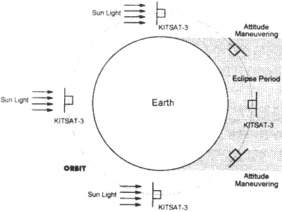
During the normal operation , the attitude of the KITSAT-3 is controlled to generate maximum power from the solar panels . During eclipse , the satellite is maneuvered to keep contact with ground control.
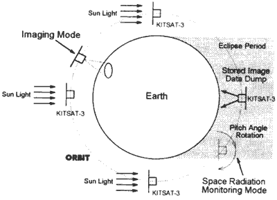
For the operation of camera system , the attitude maneuvering is performed top let the camera point the desired area prior to initiate a series of actions.

Fig.2 Attitude control for normal operation
The other attitude control mode for payloads operation is pitch angel rotation mode for the space science payload . This mode is only used after solar flare precaution for about 48 hours. During this mode , the high energy particle telescope distinguishes the kinds of particles and their levels and measures the directivity as well.

Fig.3 Attitude control for payloads operations
5.Basseline System Architecture
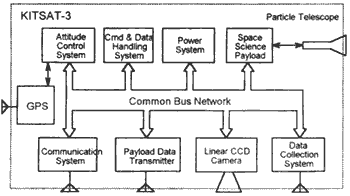
The KITSAT-3 system is based upon modular architecture . The system diagram is shown at fig.4.

Fig.4 KITSAT-3 System Architecture
All the subsystems are connected to others through bus network provides 38.4 kbps data communication with fault free data communication protocol. Each subsystem has its own telemetry and telecommand function , through C&DH is primary . This configuration gives a lot of freedom to expand functions for future mission and simplicity to interconnect .
6 .Mission Timelines
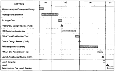
The KITSAT-3 program has been initiated in Augast,1994 as 2.5 years time span . Until the end of 1995. the SaTReC will complete the manufacturing and test of KITSAT -3 engineering model. It also includes qualification test for new launcher. The KITSAT-3 flight model will be flight ready at the end of 1996.

Fig.5 KITSAT-3 Mission Timelines
The flight schedule is under negotiation, but it will not be later than the middle of 1997. The Fig. 4 shows detailed project timelines.
7. Conclusion
Through the in-orbit test, the KiTSAT-3 satellite system will be thoroughly tested and proved. From the engineering test using KITSAT-3 system, the SaTReC will expand its capability to design next generation small satellite carrying a high resolution CCD camera and a SAR demonstrator.
The KITSAT-3 system will demonstrate state-of-technology of small satellite with low cost but competitive quality with commercial remote sensing satellites or highly expensive scientific satellites.
8. References
- S Park and S. Choi, "Space Activity at SaTReC", 2nd APC-MCSTA, 1995
- "Operations Concept Document for KITSAT-3" SaTReC Doc., 1995
- "KITSAT-3 General System Specifications", SaTReC Doc., 1995
- I. Lee, D. Sung, and S. Choi, "Experimental Multimission Microsatellites-KITSAT Series", 7th A/AA/USU Conference on Small Satellite, 1993
- S. Kim, D. Sung, and S. Choi, "A Korean Experimental Microsatellite" KITSAT-1 System" AP-MCSTA Workshop, 1992