| GISdevelopment.net ---> AARS ---> ACRS 1992 ---> Mapping from Space |
Topographical Mapping from
Stereo Satellite Data - Preliminary Findings
Mazlan Hashim,Abdul Razak
Abu Bakar
Check Zainuddin Check Jusoh,Sansudin Ahmad
Centre of Remote Sensing, Faculty of Surveying
Universiti Teknologi Malaysia, Locked Bag 791
80990 Johor Bahru, Malaysia
Check Zainuddin Check Jusoh,Sansudin Ahmad
Centre of Remote Sensing, Faculty of Surveying
Universiti Teknologi Malaysia, Locked Bag 791
80990 Johor Bahru, Malaysia
Abstract
The advent of high resolution Charged-Coupled-Device (CCD) and steerable capability of sensor on board the SPOT satellite provides necessary geometry for the restitution of 3-D vision requirements from its overlapping scenes acquired from the east and west orbit. Unlike the perspective geometry of conventional aerial photography, CCD sensor produces dynamic digital images which can be restituted digitally by auto-stereocorrelation technique. This paper reports the preliminary assessment of 3-dimensional mapping using SPOT-1 PLA data. Results of the test area covering 13km2 north and Kualal Lumpur revealed an accuracy with a standard deviation of 38.7m in planimetry and 18.6m in height. Refinement of ground control point framework and the algorithms adopted in this study is suggested to obtain the required accuracy for producing topographical maps. Due to the limitations in the system, it is suggested to restrict the area of work to consist only one particular terrain in order to achieve the goal.
Introduction
With the advent of HRV CCD sensors on board SPOT satellite with revisit and steerable capability, it has been possible to obtain stereo images for 1:5000 topographical mapping purposes. Hence SPOT images are expected to be able to provide information necessary for production of topographical maps showing planimetric details and height information.
In general, there are two basic approaches in producing topographical maps from stereo satellite data: analytical and digital. An analytical is the plotter is the main device in the analytical procedure while the technique of autocorrelation is applied in the digital method of topographical map production Paper Presented at the 13th Asian Conference on Remote Sensing, 7-11 October 1992, Mongolia.
The main input in analytical method are the elements of exterior orientation (semi-major axis and semi-minor axis of the orbit, argument of perigee, eccentricity, true anomaly and ascending node). Dowman (1989) and Gugan et. al. (1988) employed a KERN DSR analytical stereoplotter and the accuracy obtained was 6.7m planimetric and 6.5m in height whilst Konecney et. al. (1988) on PLANICOMP produced an accuracy of 17.5m in planimetry and 6.5 in height.
On the contrary, digital techniques engage the process of image matching and stereocorrelation in producing stereopairs for mapping purposes. Image matching and stereocorrelation are used in register one image onto the corresponding image thus forming stereopair. The main input are the image coordinates in pixel and the look angles of the satellite at the time of exposure. Geometric rectification is achieved by registering these image coordinates to the ground coordinates. Welch (1989, 1990, 1992) has employed this method and obtained an accuracy of 11 m in planimetry and 15 m in height.
Analytical procedures, however, needs the use of bulk instrumentation, which is very costly and the production procedure is time consuming. Therefore, this research is focused on digital approach of map production which can be applied on a PC – based processing unit. The Desktop Mapping System which is readily available at the Centre for Remote Sensing, Universiti Teknologi Malaysia will be used to achieve the objectives
Methodology
1 Data Set
A pair of SPOT PLA data acquired on the 26/12/90 and 30/12/90 with look angles of 22.80 and 19.20 and base – height ratio of 0.77 was employed. Central latitude of the data is 30 00’ 21” N for both images and central longitudes are 1010 38’ 27” E and 1010 41’ 07” E respectively.
2 Image Registration
The aim of image registration process is to obtain a stereo pair. The registration process on Desktop Mapping System (DMS), stereo correlation techniques is applies. This technique assumes that any difference between the left and right images is caused by relief displacement (Welch, 1992). Therefore, in order to minimize discrepancies of both image caused by the relief displacement, it is essential to register the right image to the left image (reference) using a selection of well-distributed control points lying at precisely measured, a least square solution is carried out to transform right image space coordinates onto left image space coordinates thus forming a stereo pair.
Figure 1 : Location Plan
Figure 2 : Methodology Applied
3 Stereocorrelation
Sterecorrelation involves the matching of pixel location in the left and right image of the stereopair. The target area of the image with the point to be matched in the centre is chosen. Assuming no relief displacement, a larger search window of the right image centered at the corresponding pixel location is also defined. The target image (correlation window) is then systematically moved in a column direction in the search area an a correlation coefficient was calculated for each move thus producing an array of correlation coefficients, each of which represents the degree of similarity of a subarea in the search area tot eh target area (Chen et al. 1990). The pixel location by which the maximum correlation is recorded indicates the match point on the right image. figure 3 explains the general procedure of stereocorrelation.
The generalized correlation coefficient adopted in this study as suggested by Chen et. al. 1991, is
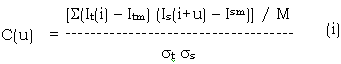
Where :
u = moving lag at column direction
C(u) = normalized cross – correlation coefficient
It(i) = pixel value at column coordinate i on the target image
Is(i+u) = pixel value at column coordinate (i + u) on the search image
Itm = mean of the pixel on the target image
Ism = mean at the pixel value on the search image/size of the target image) M = dimension of target image
The difference between the true pixel locations in x – direction represents the amount of the parallax difference (Dp). The Dp value is proportional to the elevation difference Dh between the measured point and the local vertical datum established earlier in the registration process (Welch, 1992).
4 Digital Elevation Model
The end product of the sterecorrelation is the Digital Elevation Model (DEM). This is a relative DEM in term of Dp values. For this preliminary work, a relative DEM of 100m (10 pixel) interval was calculated using the correlation window of 9 x 9 pixels. 85% of the correlation was successful. The true DEM was then derived using (ii) (Welch, 1992).

Where,
Z = the absolute ground elevation for a DEM cell at point i
a = ground elevation for the approximate reference datum as established by the image control points selected to register the stereopair.
b = Scaling coefficient, approximately the profile slope
Dp = difference in x – parallax in pixel at point i
Figure 3 : Generalized correlation procedure
Results
The control points chosen a great effect on the results that were obtained. In image remigration process, the controls have to be at approximately the same elevation to minimize the effect of relief displacement. In Malaysia, with non-homogeneous conditions, having a set of well-distributed control points is sometimes impossible and this affects the geometry of the stereopair. Therefore, from this preliminary work, it is suggested to limit the area of work to consist only one particular terrain, thus making it possible the pairing of control points as requested by the system.
In the test area, it is impossible to have a good set of ground control points of desired framework due to the scareness of the identifiable features on the satellite scene and on the ground. This factor, together with unrefined formulation of the image orbital parameters and stereo correlation, results in a standard deviation of 38.7 m (s - 6.2) in planimetry and 17.6m (s = 4.2) in height.
Radiometric effects do not affect the final outcome as so the geometric effects. To this extent, no attempt was made to correct the pairs for radiometric effects.
Conclusions
This study has demonstrated that it is possible to produce topographical maps from stereo satellite data. With the ‘crude’ and unrefined formulation adopted in image matching and stereo correlation, an accuracy of 38.7m in planimetry and 17.6m in height was achieved.
Due to the unavailability of the map accuracy of the test area, and also with no mapping accuracy standard adopted in Malaysia, comparative analysis of the results obtained could not be carried out. This, therefore, represents the early results of the study. It is hoped that by the appropriate department so that the final results can be compared.
Acknowledgements
The authors wish to acknowledge the Ministry of Science, Technology and Environment for providing the funds necessary for the research. A special gratitude must also go the Centre for Remote Sensing, Universiti Teknologi Malaysia for providing all the necessary instrument and guides in achieving the goal.
References
Borckelbank, D.C., 1991. Stereo Elevation Determination Techniques for SPOT imagery, Photogrammetric Engineering and Remote Sensing, 57 (8), pp 1065-1073.
Chen, C.F and Scarpace, F.L., 1990 Application of Numerical Matching for Photogrammetry, Paper presented at the Proceedings of ISPRS Symposium, common 4, pp 366-375.
Dowman, I.J., 1989. Mapping From Satellite Data: The State of The Art, Surveying and Mapping, 10 (5), pp 1-10.
Grabmaier, K., Tuladhar, A.M. and Verstappen, H.T. 1988 Stereo Mapping with SPOT, ITC Journal on Remote Sensing, Vol. 2 pp 149-154.
Gugan, D.J. and Dowman, I.J 1988. Topographic Mapping from SPOT Imagery, Photogrammetric Engineering and Remote Sensing, 54 (10), pp 1409-1414.
Welch, R.A and Papacharalampos, D., 1992 Three-Dimensional Terrain Visualization on Personal Computers : An Application with stereo SIR-B Images, Photogrammetric Engineering and Remote Sensing, 58(1) pp 71 – 75.
Welch, R.A., 1990. 3-D Terrain Modeling for GIS Application, GIS World, 3 (5), pp 26-30.