| GISdevelopment.net ---> AARS ---> ACRS 1980 ---> Technical Session |
Development of Microwave
Scanning Radiometer For Marine Observation Satellite-1
Y. Ishizawa, T.
Tange
National Space Development Agency of Japan (Nasada)
Hamamatsu-cho 2-4-1, Minato-ku, Tokyo 105, Japan
T. Imatani
Mitsubishi Electric Corrporation, Space Systems Dept., Kamakura Works
325 Kamimachiya, Kamakura, Kanagawa 247, Japan
National Space Development Agency of Japan (Nasada)
Hamamatsu-cho 2-4-1, Minato-ku, Tokyo 105, Japan
T. Imatani
Mitsubishi Electric Corrporation, Space Systems Dept., Kamakura Works
325 Kamimachiya, Kamakura, Kanagawa 247, Japan
Abstract
The MSR (Microwave Scanning Radiometer) is under development with target data of 1983 to be installed to the MOS-1 (Maritime observation Satellite-1) which will be launched in 1984 FY.
Introduction
The development of the MSR is in progress in the order of the Breadboard Model, Engineering Model, jProto-Flight Model and Flight Model.
In the first step, the whole Breadboard Model was manufactured and evaluated. From the test result of the Breadboard Model, we had a confidence to obtain a good performance.
The pictures of the Breadboard Model are shown in Figure 1 and the blcok diagram of the MSR is shown in Figure 2.
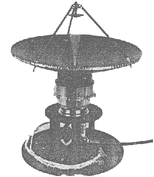
(a) Offset Cassegrain Antenna & ADM
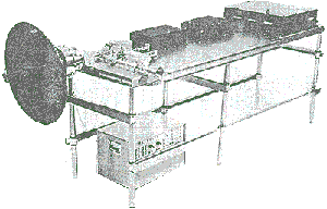
(b) Whole View of MSR.
Fig 1 Pictures of BBM.
Blcok diagram of the MSR
The MSR is composed of two Dicke type radiometers in frequency of 23.8 GHz and 31.4 GHz. The scanning is performed conically, as shown in figure 3, by rotating the main & sub-reflector of the cassegrain antenna with about 18rpm.
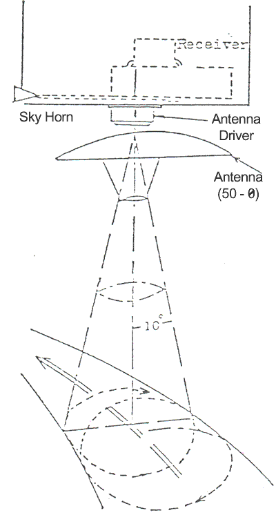
Fig 3 Diaramatic illustration of MSR scanning concept.
1. Design Consideration
- Mechanical scanning method was selected from the viewpoint of the common use for two kinds of frequencies.
- Conical scanning method was selected due to almost no influence on the attitude control of the satellite.
- Offset cassegrain antenna was selected in order to mainimize the RF losses.
- Dicke comparison radiometer type was selected to minimize the effect of the gain variation.
- SSB (Single side Band) method for the receiver using the 4 CHz band IF was selected to improve the radiometric resolution due to realizing the wide bandwidth.
- Charge/Discharge method of the integrator was selected and the ntegrating time is 10 msec/47 msec.
- Purposem
Measurement of the state of the sea surface and the atmosphere.
- Frequency Band
Channel 1 23.6 – 24.0 GHz
Channel 2. 31.15 – 31.65 GHz
- Radiometric Resolution
Channel 1. 1 K (target)
Channel 2. 1 K (target)
- ynamic Range
30 k – 330 k
- Antenna Beam Width
23.8 GHz Band 1.890 (nominal)
31.4 GHz Band 1.310 (nominal)
- Antenna Scanning Method
Continuous conical scanning
Conical scanning angle 200 + 5%
Rotating velocity 18.75 rpm (nominal)
- Data Stream
Output code Bi phase level serial
Frame rate 1 frame/3.2 sec
Bit rate 2000 bit/sec
Frame length 640 world/frame
Word length 10 bit/word
- Key Items of Performance for Breadboard Model
- Temperature control capability of the reference load (340 k) was within +0.03 k including the environmental condition.
- RF loss from antenna to receiver input was less than 1.1 dB at
31.4 GHz band and 1.0 dB at 23.8 GHz band. Moreover these values can
be improved due to conducting the gold plating.
- Noise figure of the mixer preamplifier was less than 6.6 dB at
23.8 GHz band and 7.6 dB at 31.4 GHz band. These noise figures can be
improved due to using the low noise preamplifier at 4 GHz band (NF<
1.0 dB)
- Antenna was made by CFRP and its weight was less than 900 grams. The primary horn, the sky horn and the connecting wave guide between antenna and the switching module will be made by FRP in order to isolate the heat exchange.
The test data of the temperature resolution indicate almost sam value as the estimated values and a good linearity for the input noise temperature.
The BBM test results gave us a good confidence to keep a overall performance and establish the MSR design for space use from the viewpoint of compact sin light weight, low power consumption and high reliability.
The improvement of the performance for the low loss of the RF circuit and the low noise receiver can be expected and also the establishment of the MSR desk including the satellite interface will be completed in the next step (EM).