| GISdevelopment.net ---> AARS ---> ACRS 1980 ---> Technical Session |
Geometric and Geographic
Correction for Remote Sensing Data
Dr. Shunji
Murai
Institute of Industrial Science University of Tokyo
7-22, Roppongi, Minato-ku Tokyo, Japan
Geometric and Geographic Correction for Remote Sensing Data
Dr. Shunji Murai
Institute of Industrial Science University of Tokyo
7-22, Roppongi, Minato-ku Tokyo, Japan
Institute of Industrial Science University of Tokyo
7-22, Roppongi, Minato-ku Tokyo, Japan
Geometric and Geographic Correction for Remote Sensing Data
Dr. Shunji Murai
Institute of Industrial Science University of Tokyo
7-22, Roppongi, Minato-ku Tokyo, Japan
Abstract:
Geometric and geographic correction should be made for remote sensing data in the practical application, especially in thematic mapping. The paper firstly summarizes the geometric problems in remote sensing and their corresponding geometric processing. Secondly, those experimental results are shown in this paper, which have obtained by the computer programs developed in Murai Laboratory, Institute of Industrial Science, University to Tokyo.
Introduction
Remote Sensing data includes two types of geometric errors or distortions, that is, internal error and external error. The internal error is mainly resulted from the geometric characteristics or performance of sensor, therefore, it can be coorected systematically only if the calibrations data or parameter for correction can be given.
On the other hand, the external error is resulted from the altitude of the platform and the geometric configuration of the objects. The distortions resulted from the altitutde such as the variations of three axes, that is, roll, pitch and yaw, the velocity or the altitutde can be corrected systematically only if these variations can be preciselyh measured on board.
However, as accuracy of the measurement on board is used to be not enougbh to obtain a satisfied accuracy, a sufficient number of ground control points with known coordinates should be allocated to establish a transformation between image coordinate system and geographic coordinate system.
Non linear and local distortions resulted from the terrain relief can not be corrected unless the ground height data corresponding to each pixel of the imagery can be given, or unless reconstruction of stereoscopy can be established by auto-correlation between a pair of stereo images.
Computer techniques developed for geometric or geographic correction can be applied in those subjects such as grid insertion, scene correction for remote sensing data, ortho-photo mapping or rectification of oblique photograph, three dimensional representation, mosaic, masking, closed area segmentation and so on.
Geometric correction by digital processing would be normally time consumisng and expensive subsequently, unless a carefully designed closed area segmentation and so on. Geometric correction by digital processing would be normally time consuming and expensive subsequently, unless a carefully designed computer algorithm could be established. Geometric Errors or Distrtions involved in Remote Sensing Data
Geometric characteristics of errors or distortions involved in remote sensing data should be clearly expressed in mathematical form. Two types of remote sensing data, that is, aerial photograph taken by camera and firlm and Landsat Mass data are discussed for examples in this paper. Geometric parameters which result in geometric errors or distortions in the case of aerial photograph and their corrections are summarized in Table 1 for aerial photograph and in Table 2 for Landsat Mass data.
Geometric Problems in Remote Sensing
Geometric problems in remote sensing are summarized as follows:
- Approximate correctio for quick look
only H/V ratio and/or skew distortions are corrected to produce approximately corrected image.
- Insertion of grid
Grid lines are inserted in uncorrected image by using a transformation from geographic coordinate system (x, y, z) to image coordinate system (u, v).
U = f (x, y, z)
V = g (x, y, z)
Transformation can be established by using ground control points.
- Mapping
Geometrically or geographically corrected image is produced by using system correction and transformation from image corrdinate system (u, v) to geographic coordinate system (x, y), There are two types of mapping.
Table 1 Geometric Distrortions Involved in Aerial Photograph
Parameters Distortions Correction 1. Internal Parameters 1.1 Focal Length Scale Calibration 1.2 Principal Point Decentering Calibration 1.3 Lense Distortion Radial, Tangential Calibration 1.4. Film Flatness Non-Linear Calibration 1.5. Shutter Focus F.M.C. 2. External Parameters 2.1 Attitude (Roll, Picth and Yaw) Perspective Orientation by G.C.P. 2.2. Altitude Scale Orientation by G. C. P 2.3 Terrain Relief Parallax Stereoscopy 2.4.Atomospheric Reflaction Radial Atmospheric Correction
Table 2 Geometric Errors Involved in Landsat Mss Data
Parameters Errors Correction 1. Internal Parameters 1.1 Look Angle Space of Pixel Tangent Correction 1.2. Scan Mirror Velocity Space of Pixel Angle Correction 1.3 Simultaneous Scan Step Wise Six Lines Mode 2. External Parameter 2.1 Attitude * Roll Perspective Angle Correction * Pitch Space of Line Angle Correction * Yaw Rotation Angle Correction 2.2 Altitude Scale Scale Correction 2.3 Earth Rotation Skew Shift of Lines 2.4 Terrain Relief Horizontal Parallax Ground Height 2.5. Earth Curvature Parabolic Negligible 3. Others Non-Linear G.C.P.
- Scale Correction Only the scale is corrected. Geographic grids
should be inserted in rotated image.
- Scene Correction Frame of image or data arrary of corrected image should be coincided map of data array of existing land data system. Resampling and interpolation should be applied to obtain scene corrected image.
- Scale Correction Only the scale is corrected. Geographic grids
should be inserted in rotated image.
- Ortho-photo mapping
Two types of ortho-photo mapping can be considered.
1 Two dimensional processing
In the case of flat terrain, such as coastal zone for example, rectification is only to be made for tilted photograph.
2 Three dimensional processing
In the case of relief terrain, ground heigh data corresponding to each of pixel shold be given, or auto correlation between a pair of stereoscopic photographs should be made.
- Three dimensional representation
There are two types of three representation.
There are two types of three representation.
1 Oblique projection
Three dimensional Landscape of oblique projection can be produced from two dimensional remote sensing data such as Landsat, by adding the ground height data. Hidden point processing should be done.
2 Stereo ortho-photo
One of the stereo pairs is orthogonal projection, whereas the other of the stereo pairs should be oblique projection with horizontal
- Mosaic
Geometric registration is required to produce a mosaic from several patches of images.
1 Approximate registration
In the case of flat terrain, or where terrain relief can be negligible, rotational or affine transformation is enough to make the registration.
2. Precise registration
Precise registration includes the three dimensional correction for terrain relief to produce ortho-photo and two dimensional registration subsequently.
- Masking
Masking is to sample the data which are only located in rectangular, circle or poligon.
- Closed area segmentation
Closed area which can be considered to be homogenous should be segmented by checking adjacent pizel groups with respect to mean and standard deviation.
Table 3 Summerizes geometric problems in remote sensing as mentioned above.
Table 3 Geometric Problems in remote sensing
Problem Geometric Processing 1. Approximate Correction for quick look Correction for H/V ratio and skew 2. Insertion of grid Transform from geographic coordinates to image plane u = F (x, y, z )
V = G (x, y, z)3. Maping
3.1 Scale correctionGrid should be inserted in rotated image 3.2 Scene Correction Resampling and interpolation should be madeX = F (u, v)
Y = G (u, v)4. Ortho-photo mapping
4.1 2-D processing (Flat terrain)
4.2. 3-D Processing (Relief terrain)Rectification for photo and trangent correction for scan should be made
Auto correlation between stereoscopic images or height data should be necessary5. 3-D representation
5.1 Oblique projection
5.2 Stereo ortho-photoGround height data should be combined.
Hidden point processing should be done.Parallax should be generated6. Mosaic
6.1 Approximate
6.2 PreciseAffine transformation
Ortho-photo mapping and mosaicing are necessary7. Masking Sampling of pixels in rectangular, circle or poligon 8. Closed area segmentation Grouping of segmented blobs
Scene Correction is the final goal of geometric and geographic correction for Landsat Mass data.
There are two types of procedures to achieve the scene correction.
a. Balck-box type correction
Transformation between image plane (u. v) and map plane (x, y) is construted by estimating that the function of third order polynomials can compensate resultant errors or distortions involved in LANDSAT data. Well distributed fifteen to twenty ground control points are necessary to determine the function.
b. System correction
Firstly, special image annotation data (SIAT data) are to be used to accomplish system correction for attitude, altitude, scan mirror velocity, look angle, earth rotation and so on, where the image plane (u, v) is converted to systematically corrected plane (u, v)
Secondly, pseudo affine transformation between the corrected plane (u’ v’) and map plane (x, Y) is applied to correct the residual errors as follows.
X = a1 u’ v’ + a2 u’ + a3 v’ = a4
Y = b1 u’ v’ + b2 u’ + b3 v’ + b4
Resampling the equally spaced data in the map lane as shown in Figure 2 needs interpolation of the cooresponding data in the image plane. In the case of LANDSAT MASS data, the flight direction does not coincide with true south direction. Therefore, only about 70% of the rectangular core memory area is effectively utilized for two dimensional interpolation as shown in Figure 3. However, 30% of the core memory can be saved if one dimensional interpolation is applied. For example, one frame the Japanese base map of 1:50,000 approximately corresponds to the rectangular area of 460 pixels by 280 lines, of which 70% that is, 90, 890 pixels of 128,800 pixels is only the effective data size.
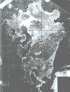
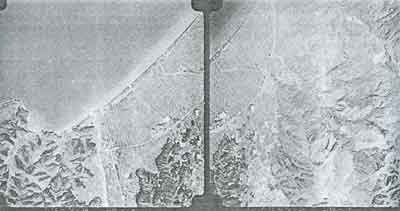
Photo 1 shows the LANDSAT MSS film of only scale correction and scene corrected imagery with the area of one degree in latitude by forty minutes in longitude in UTM system, which makes sixteen frames of the national base map of 1:50,000.
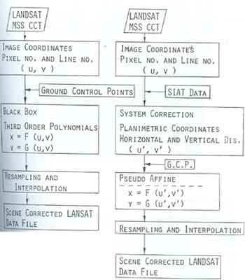
Fig. 1. Two types of Scene correction for LANDSAT MSS data
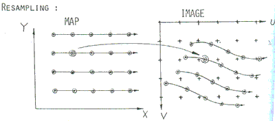
Fig. 2 Resampling and Interpolation
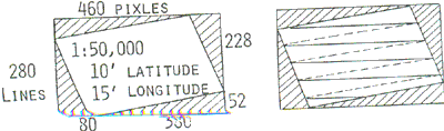
Fig. 3 Two dimensional interpolation and one dimensional interpolation
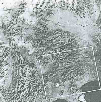
Landsat film (MSS 6)
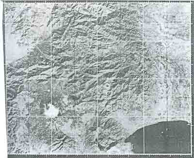
Scene Crorrected Data.
Photo 1 Scene Correction for LANDSAT MSS data
Digital Rectification of Oblique Aerial Photography in Coasal Mapping
Oblique aerial photography has those advantages such as wide coverage, avoidability of sun glittar, easiness of selecting control points, under-standability of landscape and so on, while it has disadvantage of geometric distortion.
Because of these advantages as mentioned above, oblique aerial photograph can be effectively applied to coastal mapping, if digital rectification technique which converts frm oblique photograph to vertical photograph or ortho-photo, can be developed.
The digital rectification technique has been developed by the author to produce computer generated ortho-photo from digitized oblique aerial photograph.
The procedures are as followes:
- Select the control points and measure their photo-coordinates.
- Determine the exterior orientation parameters, that is, camera position (Xo, Yo, Zo) and tilt angle or three axes (w, f, k).
- Digitize density or color tone of oblique photograph with a pixel size of 0.1 milimeter.
- Select mapping area of ortho-photo.
- Generate grid point (Xij, Yij) to be resampled in the area.
- Transform each grid point into digitized image plane. (See Figure 4)
- Interpolate the density or color tone of the grid point.
- Produce digital ortho-photo.
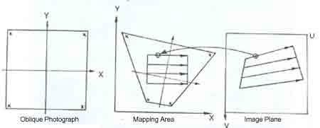
Fig 4. Transformation between Map Plane and Image Plane
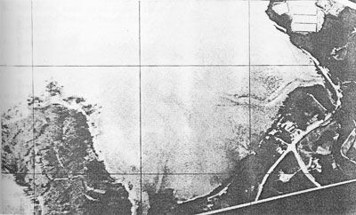
Fig 5. Digital Rectification of Oblique Aerial Photogrpah
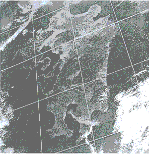
(a) original Space Photograph taken from SKYLAB.
(b) Digitally Rectified into Mercator Projection
Photo 3 Digital Rectfication of Space Oblique Aerial Photoraph.
Ortho-Photo mapping from digitzed high altitude aerial photograph with use of digital terrain data
National Land Agency has established digital data bank of ground height at the interval of 250 meters grid whole over Japan, in 1975. The scale of high altitude aerial photograph, that is, 1:80,000, can be considered to meat compatible to the interval of the digital terrain data. Therefore, if both of digitized high altitude aerial photograph and digital terrain data are combined each other, ortho-photo of 1:25,000 or 1:50,000 can be generated by computer.
The procedures are as follows:
- Select control points and measure the photo-coordinates.
- Determine the exterior orientation parameters.
- Digitize density or color tone of high altitude photograph with a pixel size of 0.1 milimeter.
- Select mapping area of ortho-photo.
- Generate grid point (Xij, Yij) with ground height Zij which is inter polated by the digital terrain data in the national data bank.
- Transform each grid point into digitized images plane. (See Figure 5)
- Interpolate the density or color tone of the gird point.
- Produce digital ortho-photo.
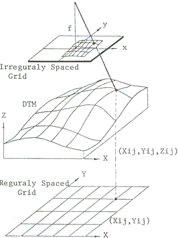
Fig. 5 Ortho-Photo Mapping with use of digital terrain model
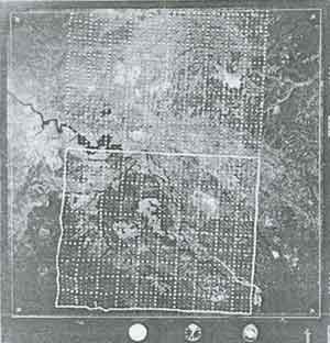
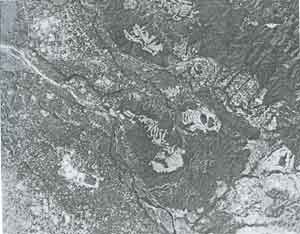
Photo 4 shows an example of original high altitude aerial photograph with inserted grid points at interval of 250 meters and computer generated ortho-photo with use of digital terrain data.
Three Dimensional Landsat Imagery
Precise geometric correction for LANDSAT data and digital terrain data in the national data bank can be combined to produce three dimensional LANDSAT imagery, that is, computer simulated oblique scenery.
The procedures to produce three dimensional LANDSAT imagery are as follows:
- Correct those geometric errors involved in LANDSAT MASS data and transform LANDSAT data onto the geographic coordinate system of the national data bank, that is, the national grid system for digital terrain data at the interval of 250 meters.
- Input of view angle and H/V ratio for three dimensional representation.
- Transform of digital terrain data in each line to oblique projection.
- Eliminate hidden area resulted from the relation between terrain relief and view angle, as shown in figure 6.
- Assign the corresponding LANDSAT data only to the visible area.
- Generate the three dimenational LANDSAT landscape with the input view angle and H/V ratio.
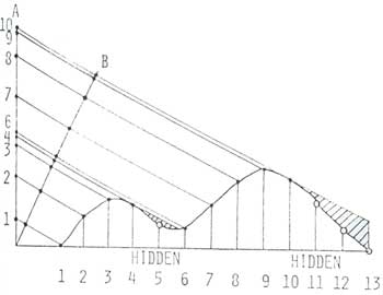
Fig. 6 Oblique projection and hidden area.
Stereo Ortho-Photo mapping form Landsat imagery and digital terrain data
With a combination of geographically corrected LANDSAT data and digital terrain data, stereo ortho-photo or pseudeo-stereoscopic imagery can be produced.
The procedures to produce the stereo ortho-photo are as follows:
- Correct those geometric errors involved in LANDSAT MASS data and transform LANDSAT data onto the geographic coordinate system of digital terrain data. Right imagery (of left imagery) should be the geographically corrected LANDSAT imagery, that is ortho-imagery.
- Generate the oblique projection with parallax, p = Htan q depending on the corresponding terrain relief H and view angle of q, as shown in Figure 7.
- Resample and interpolate equally spaced pixels from this parallaxed imagery.
- Produce the parallaxed oblique imagery as left imagery (or right imagery)
- Arrange a pair of left and right imagery and look at the pseudo stereoscopic imagery.
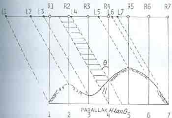
Fig. 7 Theroty of stereo ortho-photo
Vertical Angle, 0 = 300
Depression Angle, 450 0= 300
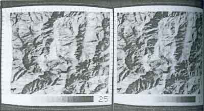
Photo 5 Pairs of Stereo-orthto-photo which were Generated on TV Monitor which use of MSS 7 and Ground Hight Data
Digital Mosaic of color aerial photographs
Digital mosaic is seriously required for colour aerial photographs or color ortho-photo map, to eliminate color tone changes between overlapped neighbor photographs.
The procedures to produce digital mosaic of color aerial photographs are as follows:
- Digitize a pair of color aerial photographs.
- Make geometric registration of right photograph onto left photograph.
- Correct the radiometric errors such as shading effect.
- Determine a seam point in each line. The seam point J is determined
so as to minmize the accumulated density difference D of width of (2 W+
1) pixels around J,
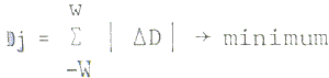
Subject to the constraint of movable range of J, that is, within a certain distance, to, from the seam pont of previous line to prevent definite seam line effect.

Where, t should be taken large range if Dj for previous line is small, and vice versa.
As the result of the above procedure, randomly scissored seam line as shown in Figure 8 can be obtained.
- Smooth the color tone around the seam point.
- Produce computer mosaic of color aerial photograph
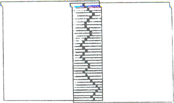
Fig 8 Seam pints of digital mosaic
A pair of original aerial photographs
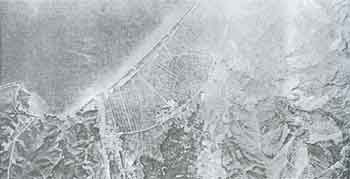
Photo 7 shows a pair of original aerial photographs and digital mosaic which was generated by CRT.
Reference:
- S. Murai, R. Tateishi, Intergration of LANDSAT CCT data and Digital Terrain Data in Cartographic Application; Procedding, ISP International Symposium com. IV, Oct. 1978, Ottawa, Canada.
- S. Murai; Digital Rectification of Oblique Photography in Coastal Mapping; Proceedings, ISP International Symposiu, com. IV, Oct. 1978, Ottawa, Canada
- S. Murai, Geometric Correction for Remote Sensing Data; Proceedings of the 5th USSR- Japan Electronics Symposium on Radiophysical Methods in Environmental Investigation, Dec. 1978
- S. Murai, T. Okuda, M. Akiyama; Digital Mosaic of Color Aerial Photographs; 14th Congress of ISP, Hamburg, 1980
- S. Murai, R. Tateishi; Three Dimensional Representation for LANDSAT MSS data; 14th Congress of ISP, Hamburg, 1980.
- S. Murai, H. Maeda; A study on Gemetric Correction for LANDSAT MASS Data; Report of the Institute of Industrial Science, the University of Tokyo, Vol. 27, No. 5, Nov. 1978.